© 2016 OJ Electronics A/S
19
INSTRUCTIONS OJ-DV | Functions
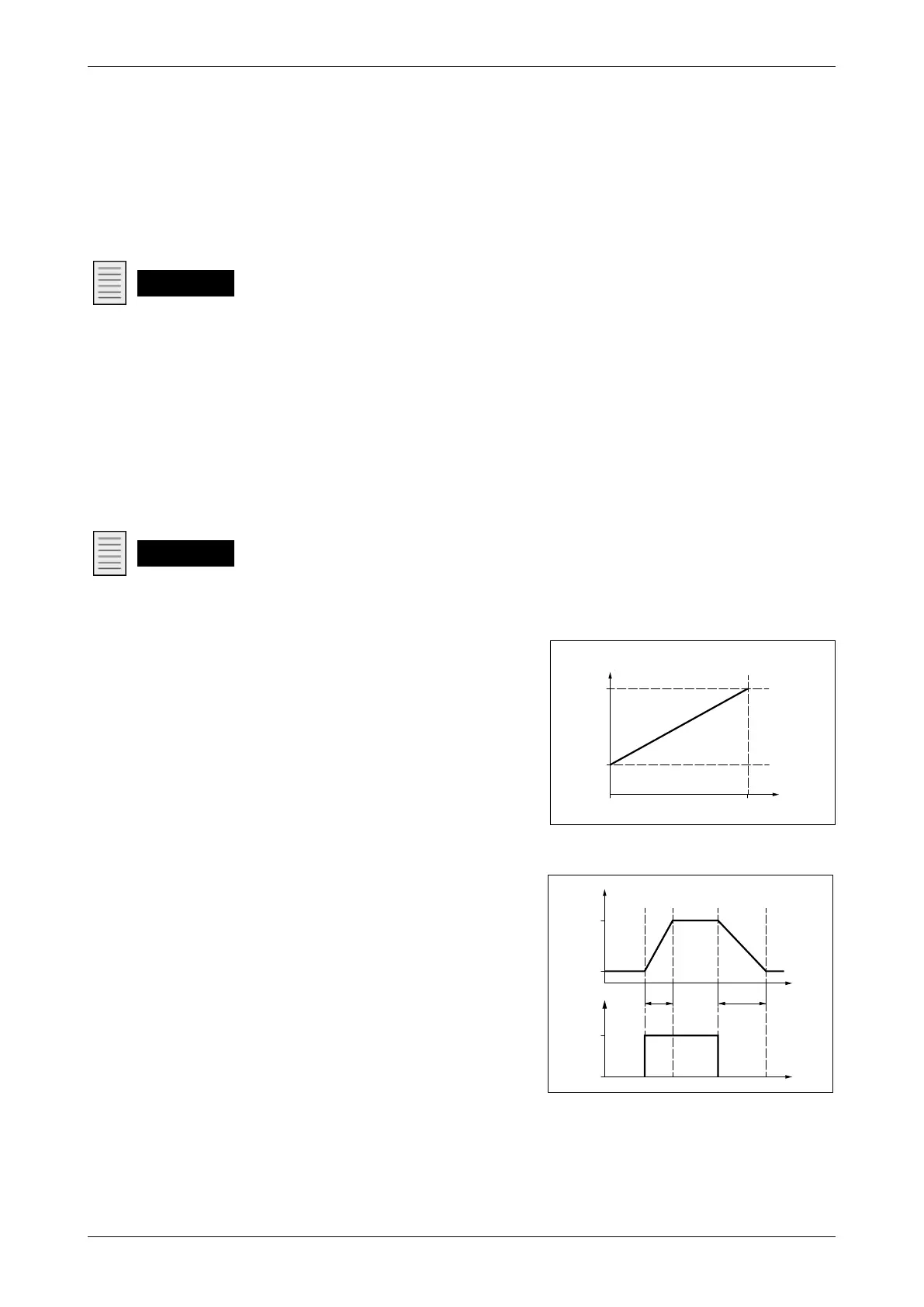
Relationship between control signal (0-10V In) and speed –
see fig. 18.1.
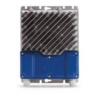
The control signal regulates motor speed between the set
minimum and maximum speeds (AC motor=Hz; PM/BLDC
motor=rpm) and the set ramp times – see fig.18.2.
18.2 Modbus control
• OJ-DV can be controlled via Modbus
commands according to the Modbus protocol.
• Control of motor speed via Modbus
communication is factory disabled.
• If OJ-DV is to be controlled via Modbus,
Coil Stat Bit register 8 must be set to ”0” =
”Modbus control”.
• Other functions, such as alarm read-out
and acknowledgement, are still possible via
Modbus even though "Modbus control" is not
activated.
• NOTE! Contact OJ Electronics A/S if you
require the Modbus protocol.
•
18.3 Switching frequency
Switching frequency is crucial in determining the
amount of audible acoustic noise emitted by OJ-DV.
The higher the switching frequency, the less audible
noise will be emitted by OJ-DV. At the same time,
however, internal losses will be increased, reducing
eciency.
18. Functions
18.1 Analogue/digital control
• OJ-DV can be controlled via analogue/digital (A/D) inputs or via Modbus.
• The factory setting is analogue/digital (A/D) control.
• Connect A/D control signals to the terminal strip, see section 13.15.1.
0-10V In
• Is used to control motor speed in relation to a 0-10V signal.
Note
• With A/D control, functions such as alarm read-out and acknowledgement are still possible via
Modbus even though "Modbus control" is not activated.
• The relationship between the 0-10V control signal and motor speed depends on the settings for
min./max. speed and ramp up/ramp down times. See figs 18.1 and 18.2.
• The ”+10Vdc”, ”0-10V In” and ”GND” terminals can be connected to a potentiometer, see
electrical connection in fig.13.15.2.
The function of the digital inputs and outputs has been defined by OJ Electronics A/S as follows:
• Din1 = Start/Stop (1 = Start)
• Din2 = Alarm reset (1 = Alarm reset)
• Dout1 = Tacho Out (1 pulse per motor revolution)
Note
The digital inputs and outputs can be given alternative functions via Modbus.
Figure 18.1
BR1014A13a
© 2015 OJ Electronics A/S
-DA
100%
0%
Setpoint
Frekvens/
omdrejninger
Max. Hz/Rpm
Min. Hz/Rpm
9.5V
0V
BR1014A13a
Frequency/revolutions
Figure 18.2
BR1014A12a
© 2015 OJ Electronic A/S
-GB
100%
0%
Time
Time
Up
Ramp
Down
Ramp
Speed out
Setpoint
Max. Speed
Min. Speed
BR1014A12a