© 2016 OJ Electronics A/S
21
INSTRUCTIONS OJ-DV | Functions
Pay special attention to the following parameters:
Minimum frequency Even if the control signal is e.g. 0% or 0.0V and the OJ-DV has an activated start signal, the motor will not
run slower than the value in this parameter.
Maximum frequency Even if the control signal is e.g. 100% or 10.0V and the OJ-DV has an activated start signal, the motor will
not run faster than the value in this parameter.
Ramp-up time Ramp-up time is the time (in seconds) from when the OJ-DV gets the start signal until the speed has been
reached according to the setpoint. The ramp-up time is used to avoid overload and damage to the controller
and motor. The ramp-up time is also used in upward jumps between speed setpoints.
If this ramp-up is too short, the OJ-DV could possibly trigger a current limit alarm
Ramp-down time. Ramp-down time is the time (in seconds) from when the OJ-DV receives a stop signal until the motor comes
to a halt. The ramp-down time is used to avoid overload and damage to the controller and motor. Ramp-
down time is also used in connection with downward jumps between speed setpoints.
If this ramp-down is too short, the OJ-DV will use power to stop or slow down the motor. This could possibly
trigger a current limit alarm from the OJ-DV.
Switch frequency Switch frequency is a parameter that has an influence on the eciency and the audible noise from the con-
nected motor and/or the OJ-DV controller.
In the OJ-DV it is possible to select “Auto”, “4 kHz” or “8 kHz”.
Activating the “Extra high” Modbus parameter makes it possible to select “Auto”, “4 kHz” or “10 kHz”.
The higher the switch frequency, the lower the audible noise from the OJ-DV controller system, but the con-
sequence of lower audible noise is decreasing eciency of the OJ-DV controller system.
In “Auto” the OJ-DV will automatically switch between “4 kHz” and “8/10 kHz”. During start-up from 0 – 60%
speed, the switch frequency will be “8/10 kHz” and this will make for less audible noise from the connected
motor and/or the OJ-DV controller. When the speed has increased and passes 60%, the switch frequency
will then switch to “4 kHz”. The noise from the fan and airflow will now drown out the audible noise from the
OJ-DV controller system.
In the speed-down sequence, the OJ-DV will switch to “8/10 kHz” when the speed of the motor passes 50%
downwards.
It is also possible to select a fixed switch frequency of “4 kHz” or “8/10 kHz”.
U-min Hz This parameter selects the voltage to the motor at minimum frequency.
Freq U-max This parameter selects the frequency to the motor at maximum voltage.
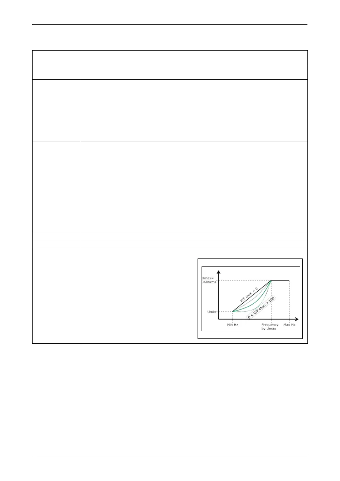
V/F characteristic The “V/F characteristic” parameter is a parameter
that makes it possible to change the ratio between
voltage and frequency for the motor.
The “V/F characteristic” is factory-set to the value 0
(zero), which means that the ratio between the volt-
age and the frequency is linear.
At the other end, the value “100” is equal to a para-
bolic relation between voltage and frequency.
For a standard fan application, the value of the “V/F
characteristic” should be 75. AC motors with poor
eciency require a higher “V/F characteristic”.
For further information about parameters in the OJ-DV, see OJ-DV Modbus protocol.
18.7 Electronically commutated mode (EC mode) – for PM and BLDC motors
The OJ-DV factory-set to frequency converter mode for standard asynchronous induction motors
(AC-IM) and the control mode is 0-10 VDC input.
This can be changed using the OJ-DV-PCTool or OJ-DCV-HTERM (Hand terminal).
The dierence between an AC-IM motor and a PM-SM/BLDC is basically the rotor.
In the PM-SM/BLDC motor, the windings in the rotor are replaced with permanent magnets, but
the control system has to be and is very dierent. Due to the permanent magnets in the rotor, they
will induce voltage in the stator windings as they rotate and as a result also voltage back to the
controller. This is what is called back EMF (EMF = electromotive force) and describes an important
and special characteristic of the motor.
The controller has to be able to handle this back EMF and that is why you cannot control a PM-SM/
BLDC motor with an OJ-DV controller in frequency converter mode.
Figure 18.6.2