3 – 4
[How to Change Parts]
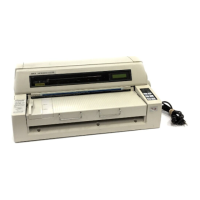
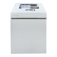
This section explains how to change parts and assemblies appearing in the disassembly diagram
below.
Printer unit
3.3.1 Printhead
3.3.2 Ribbon protector
3.3.3 Pull-up roller assy
3.3.4 Upper cover, access cover and sheet guide
3.3.5 Gear case assy
3.3.6 PC connector
3.3.7 Space motor and guide roller assy
3.3.8 Space rack
3.3.9 Carriage cable
3.3.10 Back-up roller holder assy
3.3.11 Platen assy
3.3.19 Paper pan
3.3.12 Driver board (SDDV)
3.3.13 LF motor
3.3.18 Carriage shaft
3.3.14 Operation panel PCB (LEOP)
3.3.15 Control/Power supply board (SDCT)
3.3.16 Transformer assy
3.3.17 Change lever and gears
3.3.20 Rear tractor assy
3.3.21 Rear pressure assy
3.3.22 Switch lever
 Loading...

