Do you have a question about the Oki Microline 182 and is the answer not in the manual?
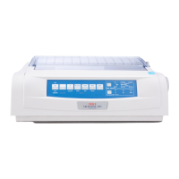
Details the standard components and assembly of the printer.
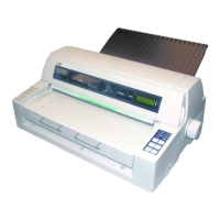
Lists and illustrates optional hardware components available for the printer.
Safety guidelines and precautions before disassembling or replacing printer parts.
Procedure for removing and replacing the printer's upper cover.
Procedure for removing and replacing the printer's main control board.
Procedure for safely removing and replacing the printer's print head assembly.
Instructions for removing and replacing the core printer mechanism.
Procedure for adjusting the critical gap between the print head and the platen.
Initial diagnostic checks to perform before attempting printer repair.
General approach and systematic steps for diagnosing printer issues.
Detailed procedures for checking electrical connections and component resistances.
Explains the operational principles of the printer's electrical circuits.
Details the microprocessor, ROM, RAM, and associated interface LSIs.
Explains the circuit responsible for activating the print head solenoids.
Describes the mechanism and control for horizontal character spacing.
Explains the mechanism and control for vertical paper movement.
Details the functions of protective and warning circuits within the printer.
Describes the printer's power supply system and its components.
Specifies the printing technology used by the standard model.
Details the printing speed capabilities at various character pitches.
Provides the physical dimensions of the ML182 and ML183 printers.
Describes the standard and optional interface types supported by the printer.
Specifies the printing technology for the IBM-compatible model.
Details the printing speed capabilities for the IBM-compatible model.
Provides the physical dimensions for the IBM-compatible model.
Describes the interfaces supported by the IBM-compatible model.