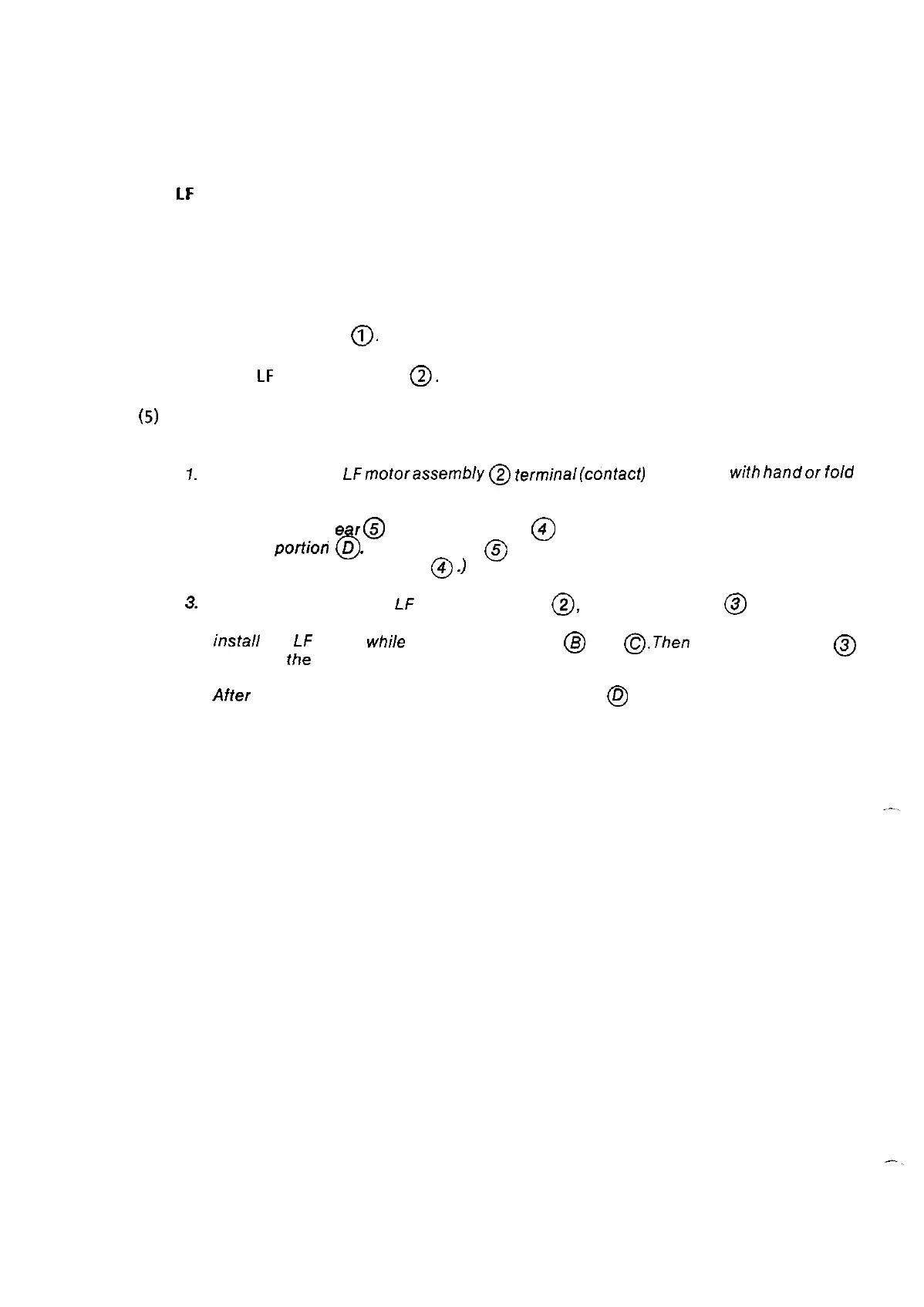
3.2.12
LF
motor assembly
(1)
Remove the upper cover (see 3.2.1).
(2)
Remove the printer mechanism. (See 3.2.11 step 7. The control board need not be
removed.)
(3)
Remove two screws
0.
(4)
Remove
LF
motor assembly
0.
(5) For reassembly, reverse the disassembly procedure.
Notes:
I.
DO not touch the LFmotorassembly
@
terminal(confacf) @directly
with
handor
fold
it and make sure that if is clean.
2.
Move the bias ge r
@
to the platen gear
@
as indicated by the arrow then engage
them at
portioh
6
D
.
(The bias gear
@
is differentiated by half of a tooth with respect
to the tooth of platen gear
@
.)
3.
When assembling the
Lf
motor assembly
0,
loosen the screw
@
fastening the
connection board and make a space between the base and connection board. Then
inStall
the
LF
motor
whi/e
pressing it against.
@
and
@.Then
tighten the screw
@
fastening
the
connection board.
4.
After
assembling, make sure that the platen gear
@
is correctly engaged and the
platen turns smoothly.
3-24