2.1.07 Alarm Circuit
Driver Circuit Alarm Processing
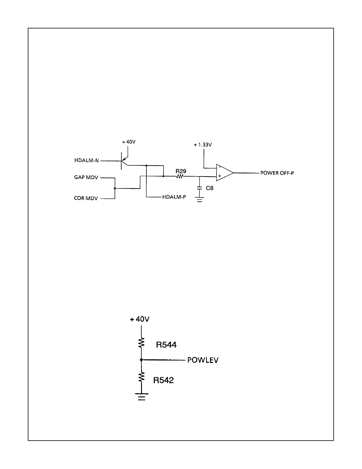
The printhead driver output and the head gap magnet output drive signals are monitored at R29
and C8. The POWER OFF-P signal is output by the comparator (Location 02C: IC2901) when
driven for more than the specified time. This signal becomes the ALM signal. The ALM signal
is sent to the power supply board and causes the DC voltages to be turned off.
Low Motor Drive Voltage Alarm
+40V is converted into the POWLEV signal (0 vdc to +5 vdc) by the voltage divider network of
R542 and R544, then input to the A/D port of the MPU. The value of this voltage is used to
control the drive time and the print speed (pass number) of the head.
2-1-07a.tif
2-1-07b.tif
Principles of Operation 2 - 14 Microline 520/521 Service Handbook
P/N 59257803