4
Table of figures
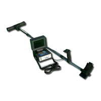
Figure 4.1: Control elements of Bionic X4 .............................................................................................. 14
Figure 4.2: Control elements of wireless headphones ............................................................................ 16
Figure 5.1: Connecting the Power Pack with the device ......................................................................... 18
Figure 5.2: Switch on the Power Pack .................................................................................................... 18
Figure 5.3: Switch on the Smart Phone .................................................................................................. 18
Figure 5.4: Place the Smart Phone into the holder ................................................................................. 19
Figure 5.5: Run the application on the Smart Phone .............................................................................. 19
Figure 5.6: Connecting the USB cable to the device ............................................................................... 19
Figure 5.7: Connecting the USB cable to the Smart Phone .................................................................... 20
Figure 5.8: Switch on the Bionic X4 ....................................................................................................... 20
Figure 5.9: Start the measurement ......................................................................................................... 20
Figure 6.1: Complete menu structure ..................................................................................................... 22
Figure 6.2: Contact between operators hand and the electrodes ........................................................... 23
Figure 6.3: Calibrating the device in bionic mode .................................................................................. 23
Figure 6.4: Measurement with the Bionic X4 .......................................................................................... 24
Figure 6.5: Triangulating with the Bionic X4 .......................................................................................... 25
Figure 6.6: Screenshot of the Smart Phone ............................................................................................ 25
Figure 6.7: Starting the cross bearing .................................................................................................... 26
Figure 6.8: Completing the cross bearing ............................................................................................... 26
Figure 6.9: Calibrating the device onto a gold object in ionic mode ....................................................... 28
Figure 6.10: Measurement in ionic mode ............................................................................................... 29
OKM GmbH
www.okmmetaldetectors.com