42
ENGLISH
2
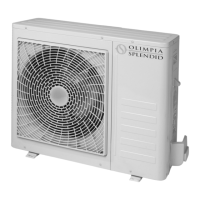
TKe e[ternal unit is supplied ZitK a mesK for covering tKe Keat e[cKange battery; tKis is envisaged for installations
accessible to tKe public. Fitting tKe mesK may cause, in tKe event of KigK Kumidity at loZ temperature (fog) or snoZ, a
build-up of ice on tKe battery ZitK reduced system performance.
2.3 OPERATING LIMITS (g.10)
The diagrams in g.10 dene the water (LWT) and outdoor air (ODT) temperature limits within which the heat pump can run in
its two modes, domestic water cooling and heating/production, and cooling only.
2.4 REFRIGERANT CONNECTIONS (g. 11, 12)
To dene the refrigerant connection lines between the internal unit and the external unit, see the table below.
OS-
CEBSH24EI
OS-
CEBCH36EI
OS-
CEBCH48EI
OS-
CEBTH48EI
OS-
CEBCH60EI
OS-
CEBTH60EI
Maximum length of
connecting pipes (m)
25 30 50 50 50 50
Limit of elevation difference
between the two units if the
external unit is positioned
higher (m)
12 20 25 30 25 30
Limit of elevation difference
between the two units if the
external unit is positioned
lower (m)
9 1220202020
Additional charge of
refrigerant per metre over 5
metres piping (g/m)
60 60 60 60 60 60
Use solely pipes with diameters that comply with the required dimensions (5/8 gas pipe, 3/8 liquid pipe).
The maximum length of the connecting lines to the internal unit must comply with table 1, topping up the charge of R410A as
envisaged (see sect. 2.4.2). Do not install the units beyond the maximum height difference permitted between the internal unit
and the external unit.
Complete the refrigerant circuit by connecting the internal unit to the external unit using insulated copper pipes.
Use solely insulated copper pipes specic for cooling purposes, supplied clean and sealed at the ends.
The refrigerant connections of the internal unit are behind the electric panel; those of the external unit are on the right-hand side
and the safety panel must be removed in order to gain access.
A 5/8 gas line internal unit
B 3/8 liquid line internal unit
C 5/8 gas line valve external unit
D 3/8 liquid line valve external unit
Identify a route for the pipes that reduces the length and the bends in the pipes as much as possible to obtain maximum perfor-
mance from the system.
Insert the refrigerant lines into a suitably sized cable routing duct (if possible with internal separator) fastened to the wall for
routing the pipes and electrical wires.
Cut the lengths of pipe about 3-4 cm longer than the required length.
IMPORTANT: cut using a ZKeel pipe-cutter only, tigKtening at small intervals so as not to crusK tKe pipe.
• Remove any burrs using an appropriate tool.
• Before aring, insert the fastening nut into the pipe (g.12A).
• Flare the ends of the pipes impeccably, without cracks, wrinkles or folds, using a special tool (g.12B).
• Manually tighten the pipe nut onto the thread of the tting.
• De¿nitively tigKten using a ¿[ed ZrencK to Neep tKe tKreaded part of tKe
¿tting stationary to prevent deformation,
and a dynamometric ZrencK on tKe nut (¿g. 13) calibrated ZitK tKe folloZing values depending on tKe size of tKe
pipes:
• Diameter 3/8’’ 34 N.m < tightening torque < 42 N.m
• Diameter 5/8’’ 68 N.m < tightening torque < 82 N.m