58
ENGLISH
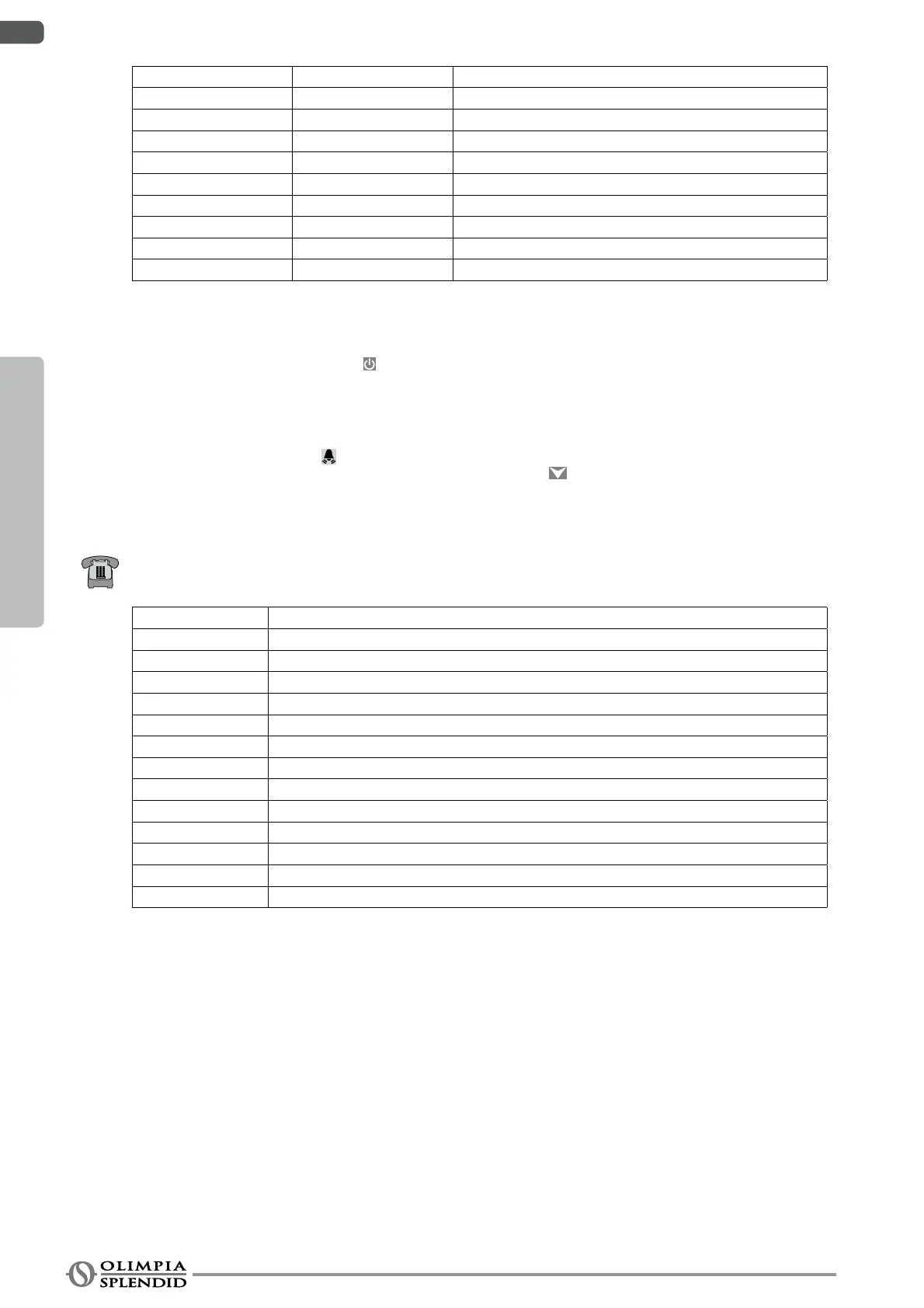
Allarme #4 A4 Outside air sensor faulty
Allarme #5 A5 Plate exchanger frost-protection
Allarme #6 A6 Flow switch alarm
Allarme #7 A7 Communication error with external unit
Allarme #8 A8 Anti-legionella cycle not performed
Allarme #9 A9 RS485 serial port communication error
Allarme #10 A10 Overcurrent protection (external unit alarm **)
Allarme #11 A11 Power voltage protection (external unit alarm **)
Allarme #12 A12 Wrong external unit phases sequence (external unit alarm **)
Allarme #13 A13 External unit sensors faulty (external unit alarm **)
** Check alarm type on external unit board sect. 3.9.2
When an alarm activates, check the cause in table 6 and remove the fault or call technical support.
To remove alarms A1 to A13, press ey8
for ten seconds or call technical support.
The control can also activate two pump maintenance and water lter alarms. Parameter Pd sets the number of running days
before the activation of the pump alarm, and parameter UF sets the number of running days before the activation of the lter
alarm.
Alarms can be activated by setting the relative parameter from 1 to 999 days, if 0 the counter is not activated.
When the alarm activates, and the machine has run for the set number of days, the display shows FiL for lter and PP for pump,
the parameter is set and the LED
switches on.
To deactivate the FiL alarm for the lter and PP for the pump, press E2
for ten seconds until the alarm clears.
3.9.2 Alarms on e[ternal unit display
The external unit control board has a two-digit display that shows any active alarms.
The table below shows the external unit alarms.
Error code Alarm Description
E0 EEPROM malfunction
E2 Communication error between external unit and internal unit
E3 External board communication error
E4 External unit temperature sensor faulty
E5 Compressor power voltage protection
E6 PFC module protection (only for 36 48 with 1 phase)
P0 Compressor head temperature protection
P1 High pressure protection
P2 Low pressure protection
P3 Compressor overcurrent protection
P4 Compressor ow temperature protection
P5 Condensation high temperature protection
P6 Module protection
3