3
NOMENCLATURE
Make sure to connect the Olympus-specified module to each connector.
The PC in use should meet the IEC60950 requirements.
If any non-specified equipment is used, Olympus cannot guarantee any performance of the system.
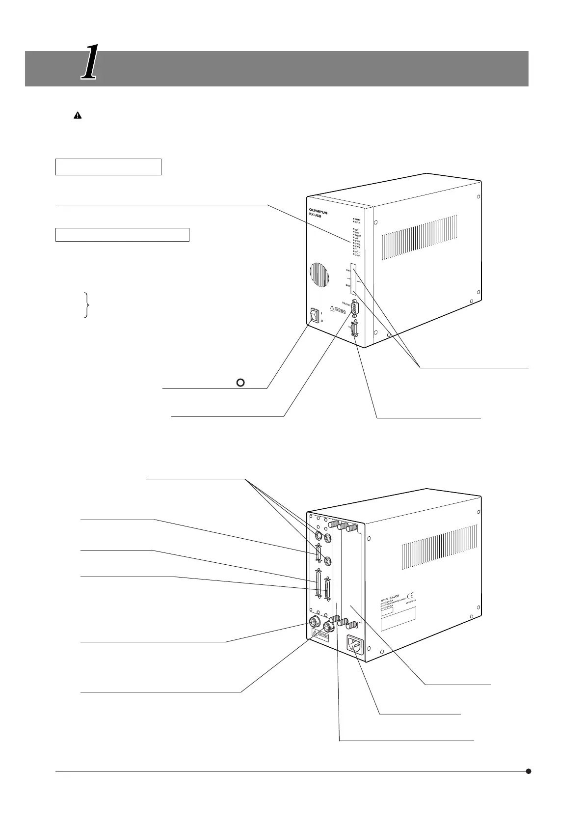
Control Box BX-UCB
Indicator LEDs
· RMT: Lights at the time of remote control (in orange).
· ERR: Blinks in case of an error (in red).
Lights during attachment (in green).
· NP: Lights when the specified motorized revolving
nosepiece is attached.
· MU: Lights when the BX-RFAA or BX-RLAA is attached.
· RSHT: Shutter of the BX-RFAA.
· AS: Aperture iris diaphragm of the U-UCD8A or BX-RLAA.
· FW1:
· FW2:
· FW3:
· TL : Top lens of the U-UCD8A.
· CDT: Turret of the U-UCD8A.
· Z/AF: Lights when the Z/AF board is attached.
Main switch ( I : ON, : OFF)
RS232C connector (9-pin male)
PC connector
DIP switches
Used for selection of operation
settings. (p.6)
HS (Hand Switch) connector
FW1/FW2/FW3 connectors
U-UCD8A connector
BX61/62 connector
RFAA/RLAA/NP connector
Transmitted light 100 W halogen lamp
housing connector
Reflected light 100 W halogen lamp housing
connector
Option slot
Z board or AF board can be installed.
Option slots (2 ch)
Power cord connector
} Each indicator lights when the U-FWT, FWO or
FWR is attached.