5
OPERATION
2-1 Control Box BX-UCB
1
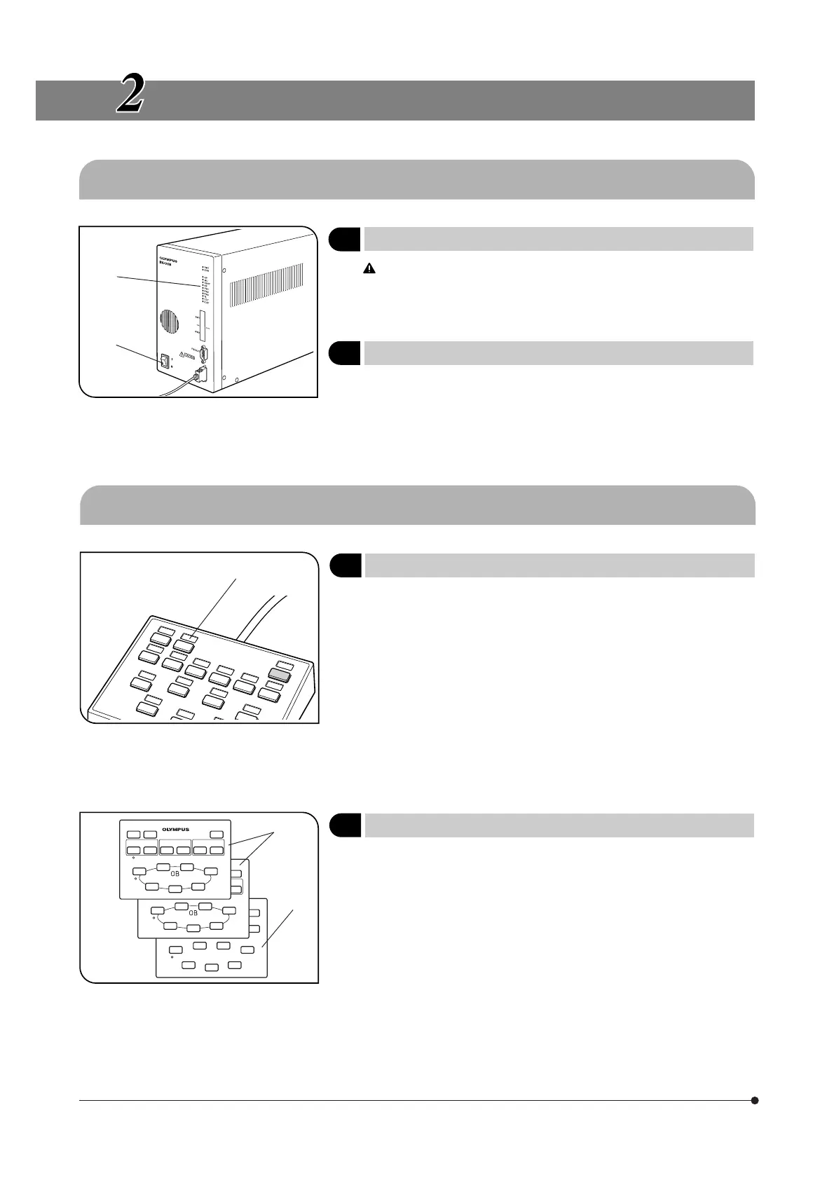
Turning Power On
(Fig. 1)
Fig. 1
Ensure that the modules to be used are connected properly.
1. Set the main switch @ to “ I ” (ON).
2. Ensure that the LED indicators ² corresponding to the connected mod-
ules are lit.
2
Functions of Indicator LEDs
(Fig. 1)
1. RMT: Lights only at the time of remote control.
2. ERR: Blinks in case of an error. At this time, the associated indica-
tors blink as described below.
3. NP to Z/AF: Each indicator lights when the corresponding module is
attached.
2-2 Hand Switch U-HSTR2
Fig. 2
1
Attaching Indication Stickers
(Fig. 2)
1. Attach each piece of the provided function indication stickers onto the
dented area @ above the button where the corresponding function is
set.
2. The indication stickers are given weak adhesive force intentionally so
that they can be removed and re-attached easily.
3. The indication stickers include two types of stickers carrying no indica-
tion on them.
· Light shield sticker: Attach to the dented area above a button with no
function set.
· Blank sticker: Create a custom indication sticker by writing the function
name with oily ink and attach to the dented area above
the required button.
Fig. 3
2
Grouping Panel Sheet
(Fig. 3)
Two sheets showing the function groups of buttons with enclosing lines
@ and a blank sheet ² are provided. Select and use the sheet that is
most convenient.
· Sheet @ (front): Used when a PC is not combined.
· Sheet @ (back): Used when direct designation of the mirror unit or filter
wheel is intended.
· Blank sheet ²: Can be used by drawing desired grouping lines with
oily ink pen.
@
²
@
²
@