10
Fig. 2
Fig. 3
Fig. 4
USING THE CONTROLS
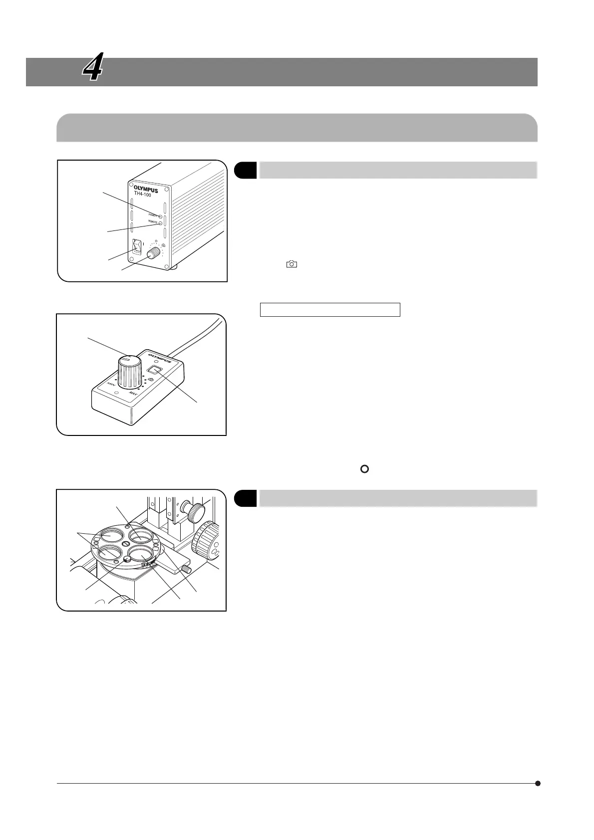
4-1 Microscope Base, Power Supply Unit (TH4)
1 Controlling the Light Intensity (TH4)
(Figs. 2 & 3)
}See the separately provided instruction manual for details.
1. Make sure that the light intensity control knob @ is set to MIN (minimum
voltage), then set the main switch ² to “ I ” (ON). (The POWER LED ³
should light up.)
2. Turn the knob @ clockwise toward MAX (maximum voltage) to increase
the intensity and brightness.
}The marking indicates the position where the optimum daylight for
color photography is obtained when the LBD filter is engaged in the light
path.
Operation Using the Hand Switch
}When the hand switch is connected (when the REMOTE LED | is lit), the
light intensity control knob @ is defeated and only the light intensity
control knob ƒ of the hand switch can be used.
The hand switch is provided with double-side adhesive tape so that it
can be attached onto a convenient position for operation.
1. After setting the main switch ² to “ I ” (ON), press the lamp ON-OFF switch
… to ON and adjust the brightness with the intensity control knob ƒ.
2. To turn the lamp OFF, press the lap ON/OFF switch … again to OFF.
#The lighting of the REMOTE LED | indicates that the hand switch is
standing by. The hand switch consumes a power of about 2.5 W
when it stands by.
When the system is not to be used for a lone period, be sure to set
the main switch ² to “ ” (OFF).
2 Using the Filter Turret
(Fig. 4)
}Filters with a diameter of 32 mm can be inserted in positions @ to |.
1. Filter positions @ and ² are rotatable. When the 32PO polarizer or 32POIR
polarizer is placed in either position, the polarizer or filter can be fixed by
using the push ring (made of white plastic).
}When filter position @ is engaged in the light path, the rotation fixing
knob ƒ comes at the front where the operation is easy.
2. Filter position ³ accepts any type of 32 mm filter.
#When using two filters together, the thickness of the lower filter should
be no more than 2 mm. Otherwise, the upper filter may drop during
rotation.
3. Filter position | accepts the 32BP775 or 32IR900 filter. As the filter can-
not be inserted unless the filter slider is removed, remove it by releasing
the insertion/removal stopper below the slider and loosening the slider
clamping screw using the provided Allen screwdriver.
@
²
³
|
ƒ
…
@
²
³
|
ƒ