III.
ASSEMBLY
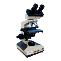
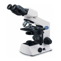
The
picture
below
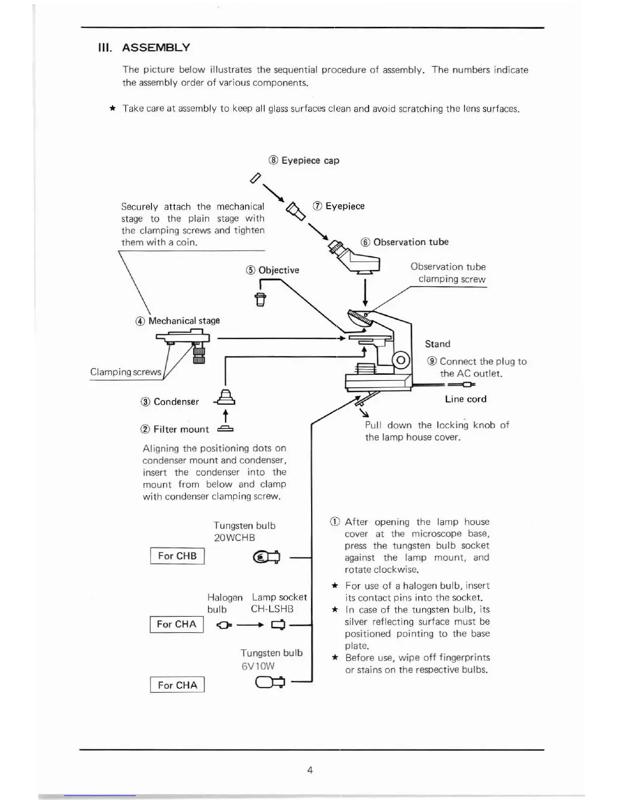
illustrates the sequential procedure
of
assembly.
The
numbers indicate
the assembly
order
of
various components.
* Take care
at
assembly
to
keep all
glass
surfaces clean and avoid scratching the lens surfaces.
® Eyepiece cap
knob
of
~'"
Securely
attach
the
mechanical II\.
(J)
Eyepiece
stage
to
the plain stage
with
""">
the
clamping screws and tighten
""-
them
with a coin.
~
Observation
tube
\
® Objective
~
Observation tube
11
! clamping screw
@ Mechanical stage
Stand
1
---------~g~~g~O~L-®~9~connect
the plug
to
Clamping screws
~
th~outlet.
® Condenser
~
A Line
cord
t
~~~
® Filter
mount
~
Pull
down
the locking
the lamp house cover.
Aligning the
positioning
dots
on
condenser
mount
and condenser,
insert
the
condenser
into
the
mount
from
below and clamp
with
condenser clamping screw.
Tungsten bulb
20WCHB
IFor CHB I
®::J
Halogen Lamp socket
bulb CH-LSHB
I
ForCHA
I
0--
Q
IFor
CHA
I
Tungsten
bulb
6V10W
Q:::J
CD
After
opening the lamp house
cover
at
the microscope base,
press the tungsten bulb socket
against the
lamp
mount,
and
rotate
clockwise.
*
For
use
of
a halogen
bulb,
insert
its contact pins into the socket.
* In
case
of
the tungsten
bulb,
its
silver reflecting surface must
be
positioned pointing
to
the
base
plate.
* Before use,
wipe
off
fingerprints
or stains on the resPective bulbs.
4