2-6
OEP-3 V1 (UC)
PS 3x6
PS 3x6
BVTT 3x6
BVTT
3x6
Harness
Clamper
SY frame
Clamper
Harness
Connector
(CN903)
Connector
(CN902)
PRT-13 board
(CN301)
PRT-13
board
(CN302)
VPR-63 board
(CN104)
Switching
regulator
Connector
(CN901)
Harness
Harness
BV 3x6
BV 3x6
Flexible flat
cable (28-pin)
Flexible flat
cable (18-pin)
Flexible flat cable (14-pin)
Flexible flat
cable (24-pin)
Connector
(CN505)
Connector
(CN304)
Connector
(CN303)
Connector
(CN302)
Connector
(CN501)
Connector
(CN306)
Connector
(CN401)
PRT-13
board
Connector
(CN601)
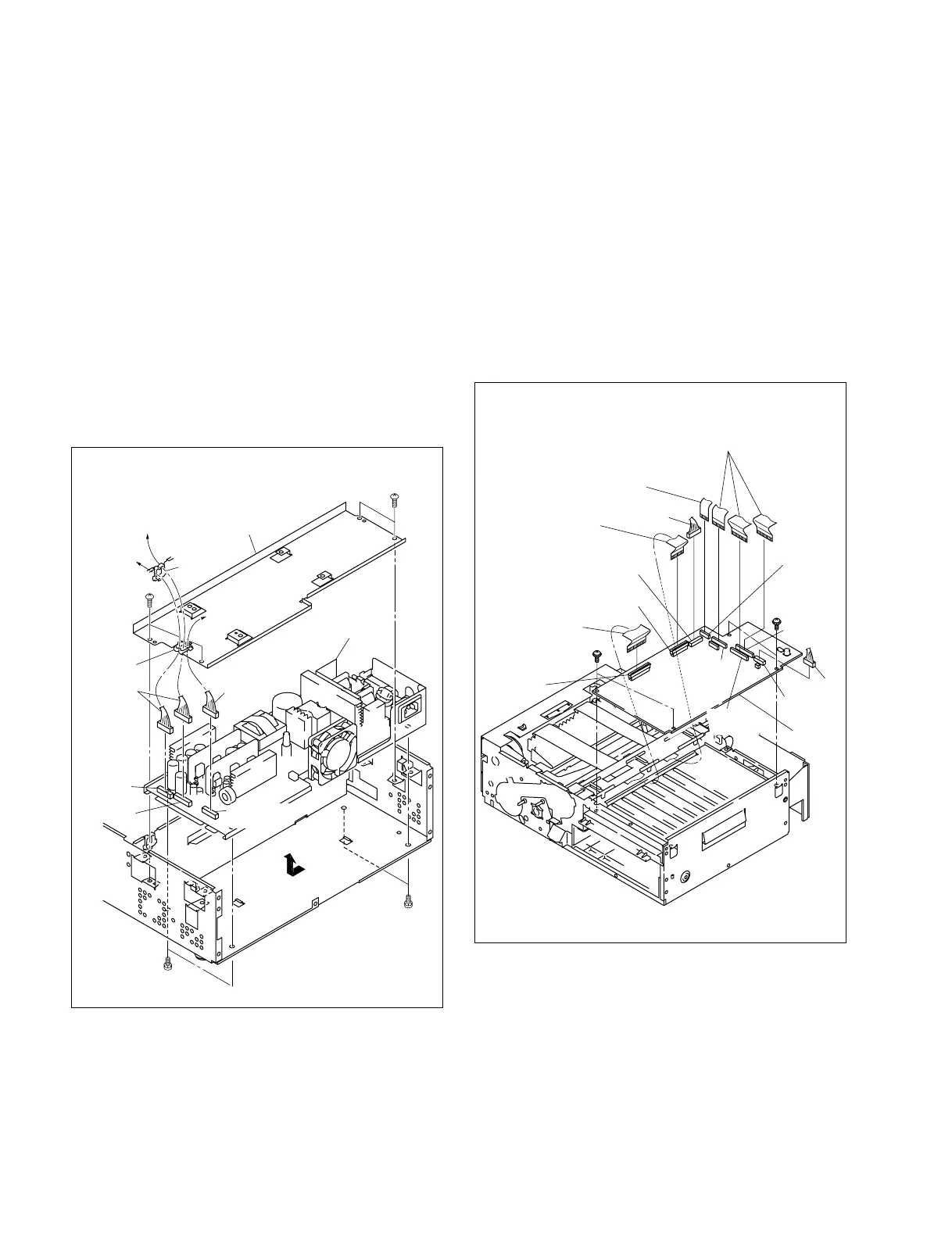
2-3-5. Replacement of Switching Regulator
1. Remove the top cover. (Refer to Section 2-2-1.)
2. Remove the VPR-63 board. (Refer to Section 2-3-1.)
3. Remove the rear panel assembly.
(Refer to Section 2-2-3.)
4. Remove the SY-282 board. (Refer to Section 2-3-2.)
5. Remove the four screws (BVTT 3 x 6), then remove
the SY frame.
6. Disconnect the harnesses from the two clampers.
7. Disconnect the three harnesses from the connectors
(CN901, CN902, and CN903) of the switching
regulator.
8. Remove the four screws (PS 3 x 6), then remove the
switching regulator.
9. Install a new switching regulator in the reverse order
of steps 1 to 8.
2-3-6. Replacement of PRT-13 Board
1. Remove the top cover. (Refer to Section 2-2-1.)
2. Remove the front panel assembly.
(Refer to Section 2-2-2.)
3. Disconnect the six flexible flat cables from the
connectors (CN303, CN304, CN306, CN401, CN501,
and CN601) on the PRT-13 board.
4. Disconnect the two harnesses from the connectors
(CN302 and CN505) on the PRT-13 board.
5. Remove the four screws, then remove the PRT-13
board.
6. Install a new PRT-13 board in the reverse order of
steps 1 to 5.