2-7
OEP-3 V1 (UC)
Connector
(CN304)
Connector
(CN303)
PRT-13
board
Hook
Hook
Hook
BVTT
3x6
BVTT 3x6
Flexible flat cable (18-pin)
Flexible flat
cable (28-pin)
Harness clamper
Cartridge
guide
BVTT
3x6
PSW
3x6
PSW
3x6
Mechanical
chassis
L assembly
Flexible flat cables
Coil spring
Head holder
Head pressure
Heat sink
Thermal
head
Thermal head
Harness
(for grounding)
2
1
1
3
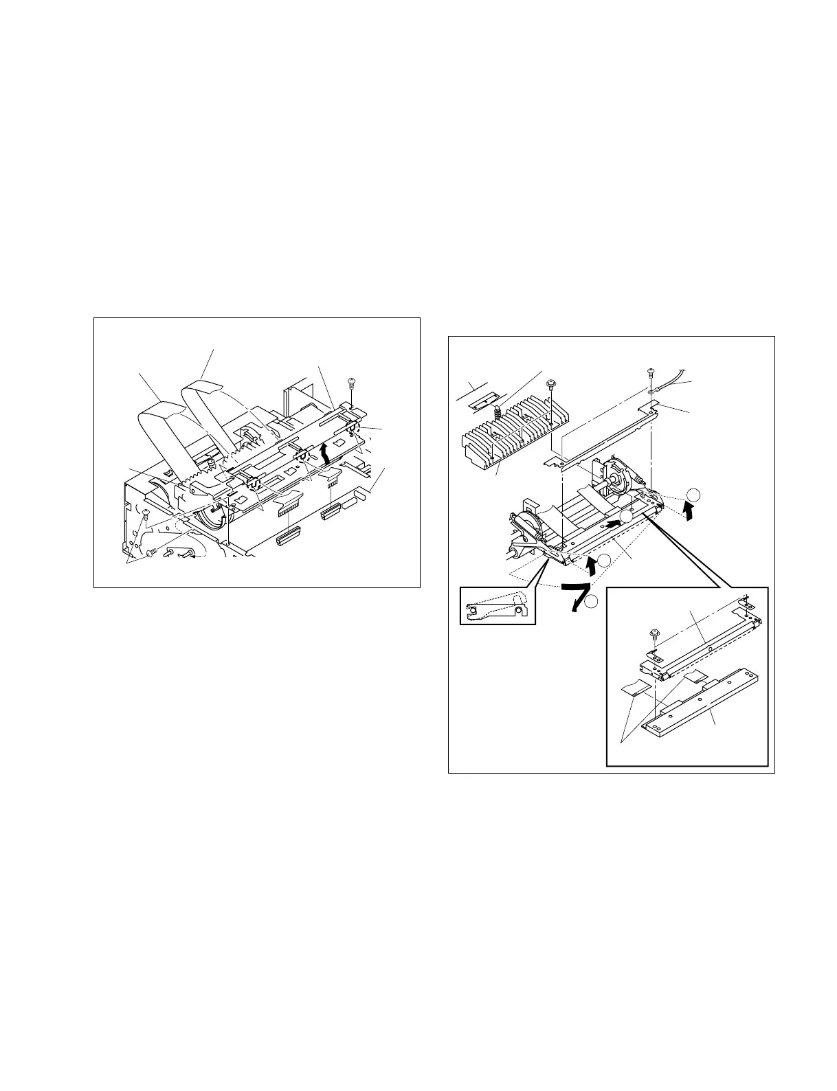
2-3-7. Replacement of Thermal Head
1. Remove the top cover. (Refer to Section 2-2-1.)
2. Remove the front panel assembly.
(Refer to Section 2-2-2.)
3. Remove the three hooks, then remove the harness
clamper.
4. Disconnect the two flexible flat cables from the
connectors (CN303 and CN304) on the PRT-13 board.
5. Remove the three screws (BVTT 3 x 6), then remove
the cartridge guide.
6. Remove the coil spring from the mechanical chassis L
assembly.
7. Remove the three screws (PSW 3 x 6), then remove
the heat sink.
8. Remove the two screws (BVTT 3 x 6), then remove
the harness (for grounding) and head pressure.
9. Move the thermal head in the order of arrows 1 to 3
and remove it.
10. Remove the two screws (PSW 3 x 6), then remove the
thermal head from the head holder.
11. Disconnect the two flexible flat cables from the
thermal head.
12. Install a new thermal head in the reverse order of steps
1 to 11.