Chapter 3 Installation and Connection
41
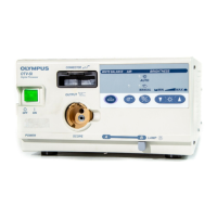
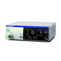
VIDEO SYSTEM OTV-SI
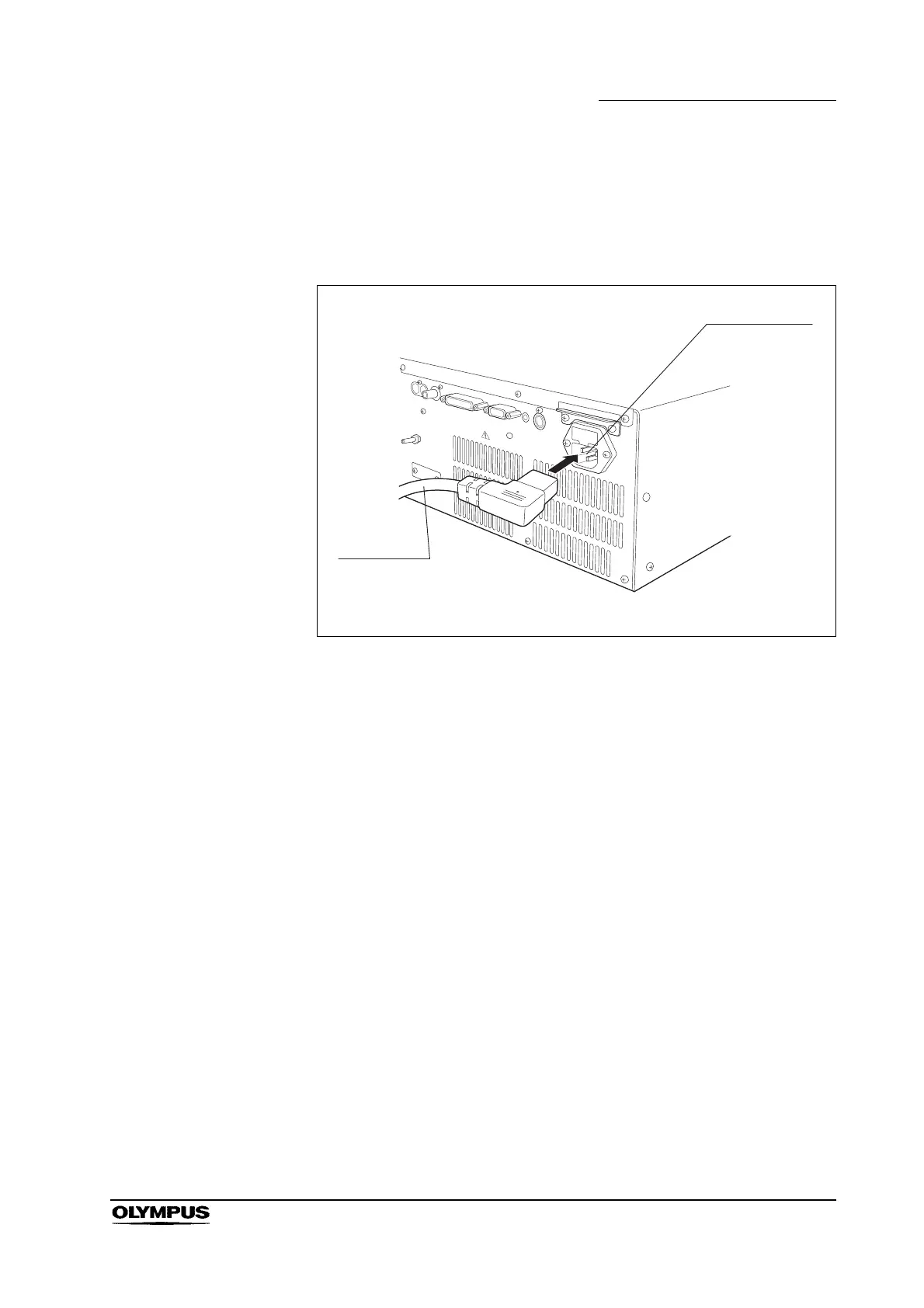
1. Confirm that the power switch is at the OFF position.
2. Connect the one end of the power cord to the AC power inlet of the video
system (see Figure 3.11), and the other end to a wall mains outlet.
Figure 3.11
3. The following ancillary equipment can be connected directly to a wall mains
outlet:
4. The following ancillary equipment must be connected via an isolation
transformer (see Figure 3.12).
Color video monitor OEV 143, OEV 203
Color video printer OEP, OEP-3
VTR SVO-9500MD
Video printers other than OEP-3/OEP
Video monitors other than OEV series