Chapter 5 Operation
53
VIDEO SYSTEM OTV-SI
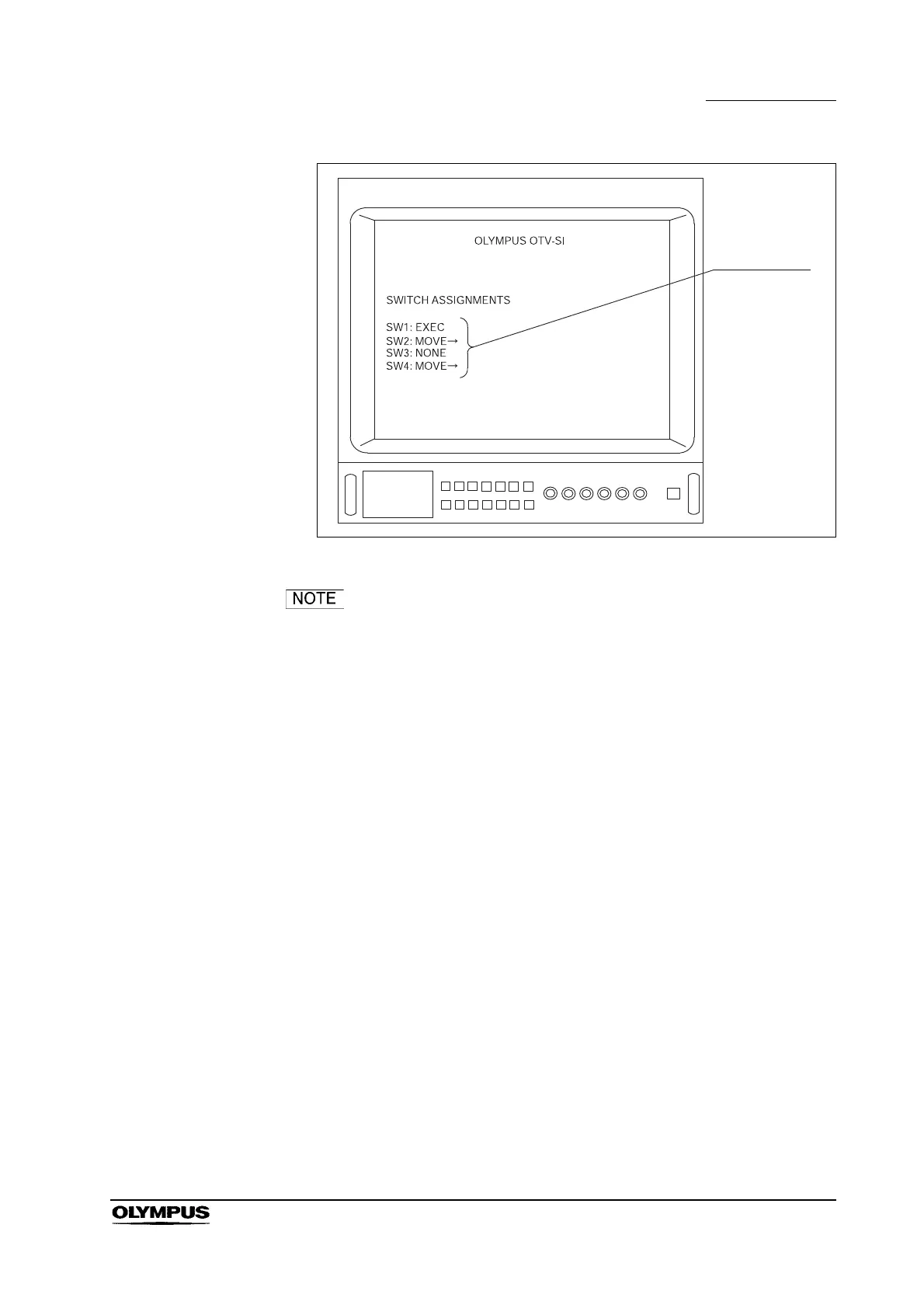
Figure 5.2
The number of “SWITCH ASSIGNMENTS” displayed (see
Figure 5.2) depends upon the number of remote control
switches on the videoscope or camera head. For example,
when the OTV-S7H-N is connected, only “SW1” and “SW2”
are displayed on the video monitor. (Refer to Section 5.9,
“Remote control switches”)
 Loading...