UES-40
Disassembly and Reassembly Procedure 3-6 ISSUE4
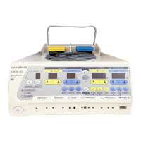
(7) Detach the E12 HARNESS from J3 of
UPHF40SS00U (monitor board) and J7 of
UPHF40OT00U (oscillation board).
(8) Detach the E24F CABLE from J1 of
UPHF40CR00U (control board) and J16 of
UPHF40SS00U (monitor board).
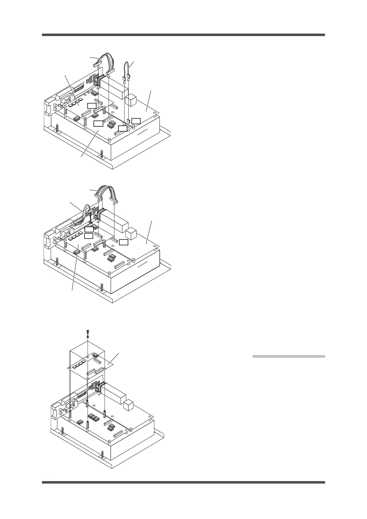
(9) Detach the E14F CABLE from J5 of
UPHF40CR00U (control board) and J4 of
UPHF40OT00U (oscillation board).
(10) Detach the SYSTEM HARNESS from J6 of
UPHF40CR00U (control board).
(11) Remove the 4 SCREWS (CCUK3x6SZ) hold-
ing UPHF40CR00U (control board), and
detach UPHF40CR00U (control board).
Phillips screwdriver (No. 2)
UPHF40CR00U
(control board)
J16
E12 HARNESS
E24F CABLE
UPHF40SS00U
(monitor board)
UPHF40OT00U
(oscillation board)
J1
J3
J7
SYSTEM HARNESS
E14F CABLE
UPHF40CR00U
(control board)
UPHF40OT00U
(oscillation board)
J5
J6
J4
UPHF40CR00U (con-
trol board)
CCUK3x6SZ
4 SCREWS