Do you have a question about the Olympus UHI-2 and is the answer not in the manual?
Details the selectable air feed modes and pressure settings for the unit.
Lists applicable gas, peripheral units, and pressure display ranges.
Covers display methods, setting range, and warning conditions for abdominal pressure.
Describes flow rate display, setting modes, and gas feed control.
Explains smoke evacuation function, operation states, communication, and electrical specs.
Outlines operating environment conditions and applicable laws/regulations.
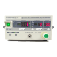
Identifies and explains all controls and indicators on the front panel.
Identifies connectors and components located on the rear panel.
Illustrates the overall system layout and connection of major components.
Depicts optional accessories and their connection points within the system.
Provides essential guidelines for safe and correct operation of the unit.
Details the signals and purpose of the RS-232C system expansion connector.
Explains the signals and function of the foot switch connector for control.
Lists common issues and their corresponding checks.
Step-by-step guide for diagnosing and resolving power supply problems.
Troubleshooting steps for issues with indicators not lighting or panel unresponsiveness.
Procedures for diagnosing and resolving issues related to gas feed and supply.
Diagnostic methods for electric-pneumatic ratio valves and solenoid valves.
Steps to identify and fix sources of noise within the unit.
Troubleshooting guide for when the smoke evacuation function is not working.
Steps to diagnose and resolve problems with the unit's relief function.
Important safety and handling advice before disassembling or assembling the unit.
Lists the specific tools and jigs necessary for maintenance procedures.
Detailed instructions for removing and reinstalling the unit's top cover.
Steps for disassembling and assembling the front panel unit.
Instructions for removing and reinstalling the unit's rear panel.
Steps for disassembling and assembling the power supply unit.
Instructions for handling the K-connector unit during maintenance.
Steps for disassembling and assembling the first pressure reducing unit.
Instructions for handling the electric pneumatic unit during maintenance.
Steps for disassembling and assembling the manifold unit.
Details front panel assembly and provides an internal piping diagram.
Visual diagram identifying parts of the front panel assembly.
Visual diagram identifying parts of the top cover and chassis assembly.
Visual diagram identifying parts of the rear panel assembly.
Visual diagram identifying parts related to the flow sensor assembly.
Visual diagram identifying parts of the regulator assembly.
Visual diagram identifying parts related to the unit's tubing.
Diagram illustrating the routing and connection of internal cables.
Comprehensive list of parts with numbers, names, and specifications.
Specific listing of screws, nuts, and washers used in the unit.
| Brand | Olympus |
|---|---|
| Model | UHI-2 |
| Category | Medical Equipment |
| Language | English |