Do you have a question about the Olympus EVIS X1 and is the answer not in the manual?
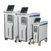
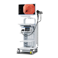
Visual representation of the system components and their connections.
Guidance on adjusting shelf height for optimal device placement.
Ensuring devices fit within the dimensions of the shelf plates.
Information on the maximum weight capacity for each shelf.
Details on device power consumption and isolation transformer limits.
Safety guidelines for connecting SDI cables, emphasizing electrostatic protection.
Connections for video output and input ports on the CV-1500 unit.
Connections for remote control and peripheral device interfaces.
Configuration options for saving exam images and capture areas.
Procedures for recording external images simultaneously or exclusively.
Instructions for connecting and operating the compatible keyboard.
Wiring and configuration details for the OEV321UH monitor.
Wiring and configuration details for the OEV262H monitor.
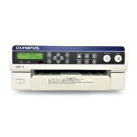
Wiring and setting information for the OEP-6 peripheral device.
Connection and configuration for the IMH-200 video recorder.
Wiring and settings for the nCare (ISM Product).
Connection and configuration details for the UPD-3 device.
Connection and configuration details for the PSCU device.
Decision tree for selecting the appropriate EU-ME2 connection type.
Decision tree for selecting the appropriate EU-ME1 connection type.
Overview of EU-ME1 configurations when using a single monitor.
Overview of EU-ME1 configurations when using multiple monitors.
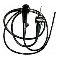
Compatibility and connection requirements for 180/260 series scopes.
Detailed procedures for connecting various cables to the CV-190/190PLUS/290.
Wiring and settings for connecting CV-190/190PLUS/290 with OEV321UH.
Wiring and settings for connecting CV-190/190PLUS/290 with EU-ME2 Type A.
Wiring and settings for connecting CV-190/190PLUS/290 with EU-ME1 Type A.
Standard setup for connecting ENDO-AID, CV-1500, and OEV321UH.
Setup for connecting ENDOBASE with the system components.
Alternative wiring configuration using OIP-1 and UPD-3.
Wiring configuration for OIP-1, CV-1500, UPD-3, and IMH-200.
Wiring configuration for OIP-1, CV-1500, UPD-3, and IMH-10/20.
Wiring setup for OIP-1, CV-1500, UPD-3, and nCare.
Wiring setup for OIP-1, CV-1500, UPD-3, nCare, and EUS.
Wiring setup for CV-1500, OEV321UH, OIP-1, and PSCU.
Wiring setup for CV-1500, OEV321UH, OIP-1, PSCU, and nCare.
Wiring setup for CV-1500, OEV321UH, OIP-1, PSCU, and HVO-400ST.
Wiring setup for CV-1500, OEV321UH, OIP-1, UPD-3, and PSCU.
Wiring setup for CV-1500, OEV321UH, OIP-1, UPD-3, PSCU, and nCare.
Wiring setup for CV-1500, OEV321UH, OIP-1, UPD-3, PSCU, and HVO400.
Table illustrating image storage based on user settings and modes.
Image storage configurations for US center with Wiring Types A and B.
Image storage configurations for US center with Wiring Types A1 and B1.
Image storage configurations for US center with Wiring Types E1S and E1Y.
| Brand | Olympus |
|---|---|
| Model | EVIS X1 |
| Category | Medical Equipment |
| Language | English |