DISASSEMBLING/ASSEMBLING PROCEDURE
1
st
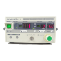
pressure reducing
unit
Electric pneumatic
unit
K-connector unit
UPUH15U flow rate sensor
Downward, Pressure sensor
Manifold unit
UHI-2 Piping Diagram
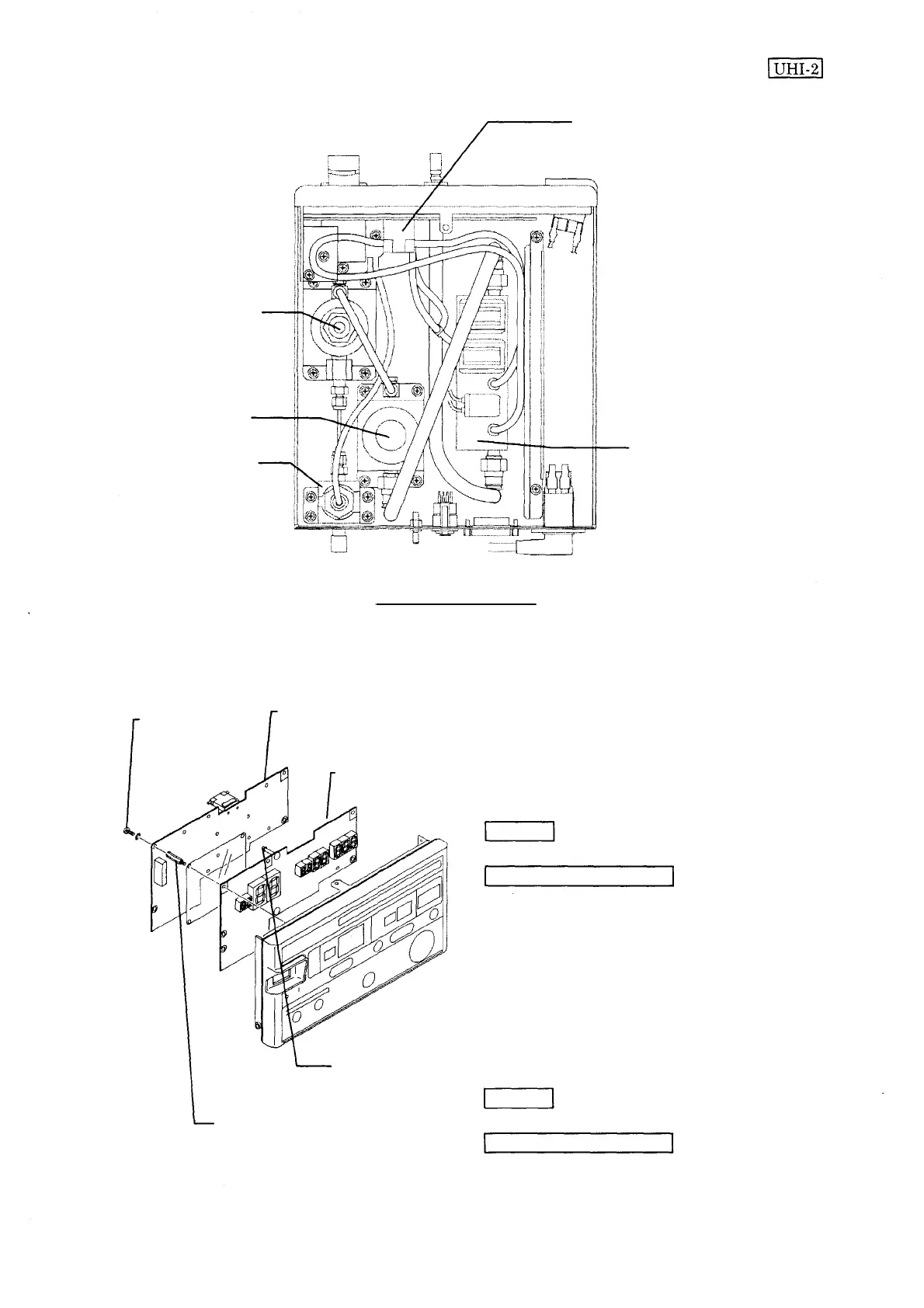
3-9 Front panel unit
HCBK3x6SA
UPUH15U
UPUH25U
Disassembling
1. Remove the screw HCBK3x6SA (6 pcs.)
which secure the UPUH15U.
2. Remove the claw of the spacer which
secures the UPUH15U.
3. Remove the spacer 1 (6 pcs.) which secure
the UPUH25U.
Spacer
Assembling
1. Secure the UPUH25U with the spacer 1 (6
pcs.). Lay the M-sheet in the position
specified on the left when securing the
UPUH25U.
2. Secure the UPUH15U with the screw
HCBK3x6SA (6 pcs.).
Spacer 1
Spanner
Philips screwdriver No. 2
Spanner
Philips screwdriver No. 2
3-7
 Loading...