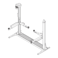
GRUPPOSTRUTTURAMOBILE
Écostituitodaduetraverseedaduepedane.
Ognitraversascorreverticalmentetraduecolonne.
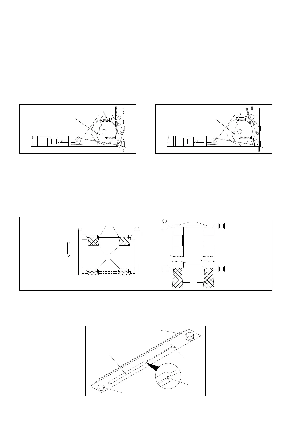
Comesivedeinfig.7,alledueestremitàdiognitraversasonofis
-
sati:
-lepuleggedirinvio(1)dellafunedisollevamento,
-gliinnestimeccanicidisicurezza(martelletti)(2e3).
Ilmartellettodistazionamento(pos.3)siinserisceautomaticamen
-
tedurantetuttalafasedisalitaenellostazionamento.Deveesse
-
redisinseritoelettricamentedurantelafasedidiscesa.
Incasodirotturadellafune,siazio-nailmicrointerruttorefuni(4)
cheprovocailbloccodellaparteelettricadelponteel’inserimento
delmartellettodistazionamento,pertantodellasuapartemobile
nonchèdelcarico.
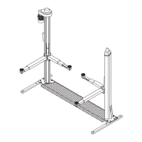
Leduepedaneportaveicoli(Fig.9)appoggianosulletraverse.
Lapedanasinistra(1)èfissa,mentrelapedanadestra(2)èmobi
-
leepuòscorrereorizzontalmenteperadattarsiallediversecarreg
-
giatedeiveicoli.Entrambesonodotatedibordiinterni(3)diconte
-
nimentodeipneumaticidelveicoloediarrestifissidisicurezza(4)
cheimpedisconoalveicolostessodioltrepassareaccidentalmente
lafinedellapedana;lerampediaccesso(5),incernieratesullepe-
dane,siposizionanoverticalmentequandolepedanesalgono,
bloccandoinmanieradefinitivailveicolo.
Fig.9 PedaneeTraverse
All’internodellapedanalatoco
-
mando(Fig.10),conaccessodal
sololatoinferiore(latosuolo),
sitrovano:
-ilcilindroidraulicodisollevamen
-
to(1);
-lavalvolaparacaduteodiblocco
(2);
-ilgiogodiattacco(3)dellefunidi
acciaio;
-duegruppipuleggedirinvio(4)
dellefuni.
Fig.10- Interno pedana fissa
MOVABLESTRUCTURE
Themovablestructureconsistoftwocross-piecesandtwoplat
-
forms.
Eachcross-piecetranslatesverticallybetweentwoposts.
Asshowninfig.7,theendsofthecross-piecesarefittedwiththe
followingparts:
-returnpulleys(1)fortheliftcable,
-mechanicalsafetydevices(wedges)(2and3).
Thewedge(pos.3)willengageautomaticallyduringliftingand
whentheliftisraised.
Incaseofbreakageofthecable,thecablemicroswitch(4)causes
thelockoftheliftelectricalpartandtheengagementofthesafety
wedge,thereforeitstopsthemovablepartandtherelevantvehic
-
le.
Thetwoplatforms(Fig.9)aresupportedonthecross-pieces.
Theleftplatform(1)hasnoadjustment;therightplatform(2)is
freetoslideacrossthewidthoftheliftingareatoadapttothetrack
widthofthevehiclebeinglifted.
Bothplatformshaveinsidekerbs(3)tokeepthevehicletyresfully
ontheliftingsurface,andfixedwheelstops(4)tostopthevehicle
fromgoingbeyondtheendsoftheplatforms;
Theaccessramps(5),pivotedtotheplatforms,automaticallyre
-
achaverticalpositionwhentheplatformslift,therebysecuringthe
vehiclealsofromtheaccessend.
Fig.9 Platforms and cross-pieces
Thefollowingcomponentsareloca
-
tedbeneaththefixedplatform(Fig.
10),andareaccessibleonlyfrom
underneath:
-hydraulicliftcylinder(1);
-parachutesafetyvalve(2);
-cleviscoupling(3)forthesteel
cables;
-twocablereturnpulleyassemblies
(4).
FiIg.10 Interiorofthefixedplatform
8
Fig.8
Abb.8
4
1
3
1
3
2
3
2
3
1
4
4
Fig.7
Abb.7
4
1
3
 Loading...