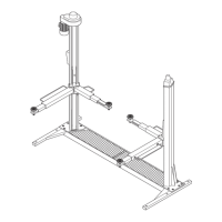
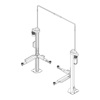
Posizionarelecolonneall’estremità
delletraverse(pos.5-6,Fig.39)se
-
guendolanumerazioneeloschema
dellafigura39.
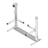
Infilaredall’altodellecolonneleaste
disicurezza(12)facendolepassare
tralaparteposterioredelletraverse
(5-6)edipernidiguida(13)comein
figura43.
Verificarecheleastedisicurezzasia
-
nodiritte.
Montareleastedisicurezzaconi
bordiarrotondatidelleasoleversola
partefrontaledellecolonne.
Fig.43 Sedediinserimentodell’astadi
sicurezza
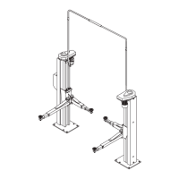
TogliereidadiM20(pos.25,Fig.42)elerosetteØ21x37(26)dall’e
-
stremitàdellefunieinserireitermi
-
nali(19)dellestessenegliappositi
foridellepiastresuperioridelleco
-
lonne.
Fig.42:avvitaresuiterminali(19)i
dadi(25)elerosette(26).Durante
questaoperazioneéimportanteve
-
rificarecheisensori(17)sianocor
-
rettamenteposizionatisullefuni(18)
figura45.
Fig.45 Posizionamentodeisensorifune
ALLACCIAMENTOIMPIANTOIDRAULICO
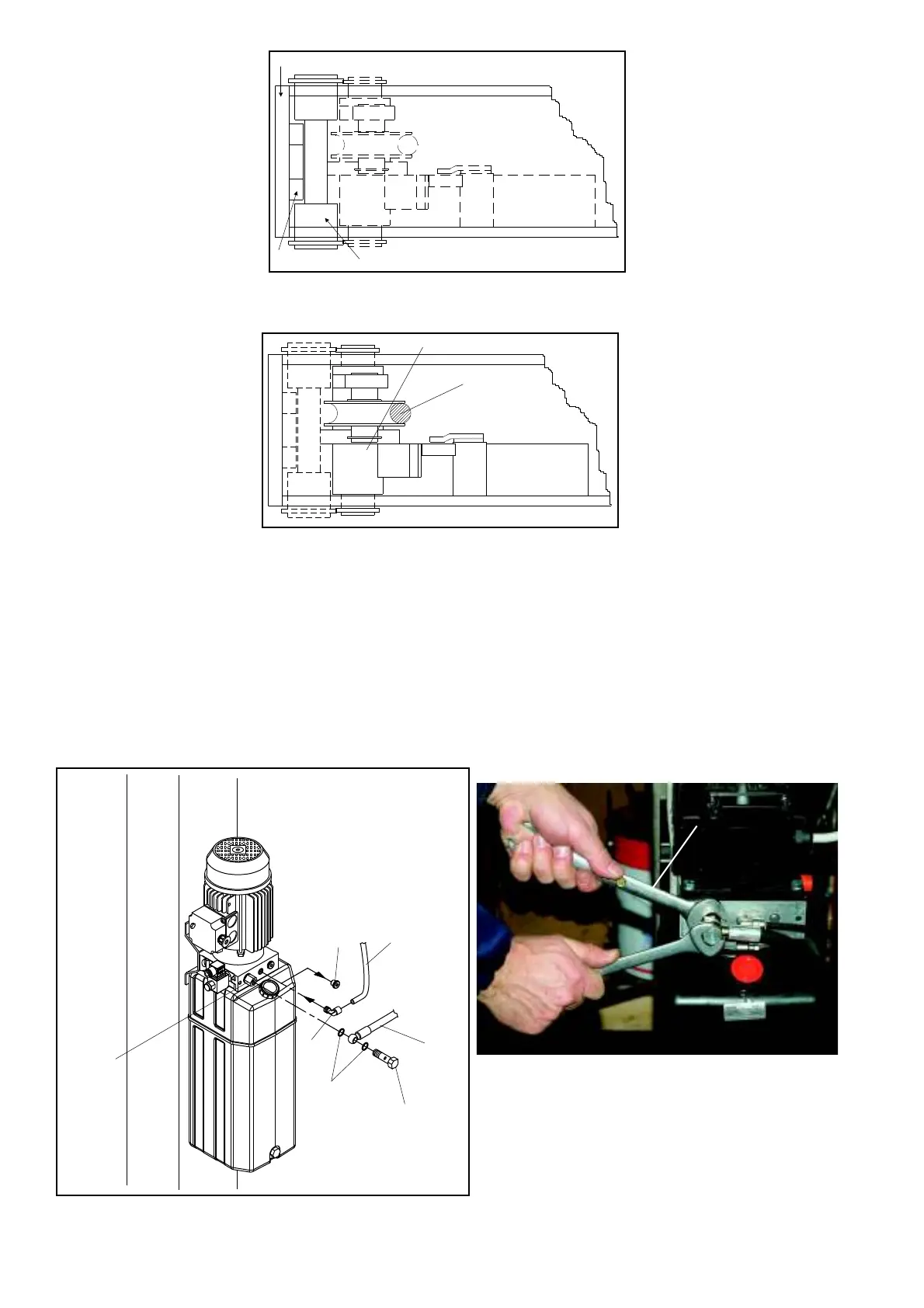
Fig.46:Togliereiltappo(1)dalcorpodellacentralina,avvitareil
raccordo(2)einserirenellostessoiltubodisfiato(3)collegatoal
cilindro.Collegareiltuboingommaaltapressione(4)alraccordo
(5)premontatosullacentralinaconlerondelle(6)elaviteforata
(7)indotazioneserrandoloafondo.
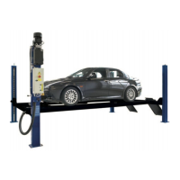
I ATTENZIONE
Tenerefermoilparticolare5Fig.46conunachiave(6Fig.46a).
Fig.46 Allacciamentoimpiantoidraulico
Fig.46 Hydraulicsystem
Positionthepostsattheendofthe
cross-pieces(pos.5-6,fig.39)obser
-
vingthenumberingandthelay-out
showninfigure39.
Fitthesafetyrods(12)fromthetop
oftheposts,insertingthembetween
therearfaceofthecross-pieces
(5-6)andtheguidepins(13)as
showninfigure43.
ChecktheSafetyrodsarestraight.
FittheSafetyrodswiththerounded
edgesoftheslotstowardsthefront
oftheposts.
Fig.43 Housing for fitting safety rod
RemovetheM20nuts(pos.25,fig.42)andthe21x37washers
(26)fromtheendsoftheliftingcables
andinstalltheterminalblocks(19)in
therelevantholesonthetopplatesof
theposts.
Fig.42:screwthenuts(25)andwa
-
shers(26)ontotheterminalblocks
(19).Duringthisproceduremakesure
thatthesensors(17)arecorrectlypo
-
sitionedontheliftingcables(18)as
showninfig.45.
Fig.45 Positioning of lifting cable sensors
HYDRAULICSYSTEMCONNECTION
Fig.46:Removetheplug(1)fromthebodyofthehydraulicpower
unit,screwtheunion(2)initsplace,andfitthebreatherpipe(3)
connectedtothecylinder.Connecthighpressurerubberhose(4)
totheunion(5)mountedonthehydraulicpowerunitwiththewa-
shers(6)andthedrillsrew(7)toequipmentandtightenitfully
down.
I
WARNING
Keepthedetail5Fig.46lockedusingawrench(6Fig.46a).
Fig.46a
28
1
3
7
4
6
5
2
6
12
13
5-6
14
18