ALLACCIAMENTOIMPIANTOELETTRICO
Primadelcollegamentoelettricoverificareche:l’impiantodi
alimentazionealsollevatoresiadotatodelleprotezioniprevi
-
stedalleNormeVigentinelpaeseincuilostessovieneinstal
-
lato.
Prevedereprotezioneda10Aperfunzio
-
namentotrifasee16Aperfunzionamento
monofase.
Eseguireilcollegamentodelcircuitoelettrico
deimicrointerruttorifuni,allacciandosinelle
appositescatolediderivazioneposteametà
delletraverseedeffettuandoicollegamenti
comeindicatonelloschematopografico.
Ilcavoelettricoinuscitadalquadrocontras
-
segnatoconinumeri3-4vacollegatoalmi
-
crointerruttorefinecorsasalitasulcontatto
NC.
Ilcavoelettricoinuscitadalquadrocontras
-
segnatoconinumeri0-7vacollegatoall’e
-
lettrovalvola.
Collegareifilideglielettromagnetidisgancio
deimartellettinellescatolediderivazione
posteametàdelletraverse,riferendosi,peri
collegamenti,alloschematopografico.
Aprireilquadroelettricoedinserirel’appositocavodialimentazio
-
ne(sez.min.4x4mm)attraversoilrelativopassacavoche,inen
-
trambiimodelli,èpostonellapartesuperioredelquadroelettrico.
Collegareilcavoaimorsettipresentinellaparteinferioredelqua
-
dro,compresoquelloditerradicoloregiallo/verde.
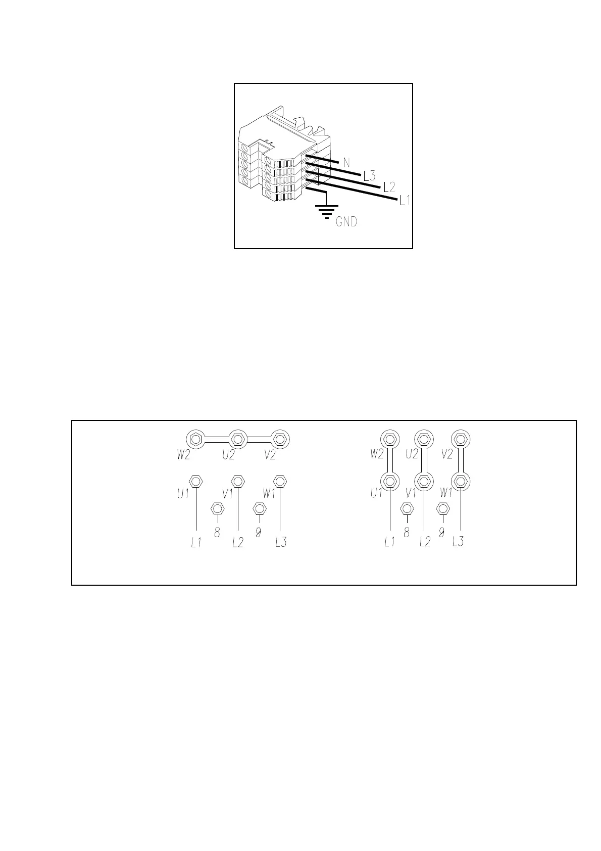
Aprirelascatoladeicontattidelmotoreedeffettuareilcollegamen
-
tocomeindicatoinfigura48,asecondadellatensioneconcuiver
-
ràalimentatoilponte.
Collegarelaprotezionetermica(Rif.8-9Fig.48).
Ilquadroelettricovienepredispostodalcostruttoreperilfunziona
-
mentoa400Vtrifase,pertantosesidesiderafarfunzionareilpon-
tea230Vtrifase,occorrecambiareilcollegamentosultrasformato-
re(vederemorsettierasultrasformatorestesso).
Fig.48collegamentimotoreetrasformatore
Unavoltaaccertatichetuttocorrisponda,chiudereilquadroepro
-
vare,salendo,ilsensodirotazionedelmotorechedeveessere
ugualeaquelloindicatosullarelativaetichettapostasulmotore
stesso.
Seilsensodirotazionenoncorrispondeconquelloindicatodalla
freccia,riaprireilquadro,invertireduefilidellefasiagganciate
comeinfigura47,richiudereilquadroeverificareilsensodirota
-
zione.
I
ATTENZIONE
TUTTELEOPERAZIONIINDICATESOPRADEVO
-
NOESSEREESEGUITEUNICAMENTEDAPER
-
SONALESPECIALIZZATO.
ELECTRICALSYSTEMCONNECTION
Beforeconnectingtheelectricsystem,makesurethat:thepo
-
wersupplyplanttotheliftisequippedwiththeprotectionde
-
vicesrequiredbycurrentstandardsinthecountrywherethe
machineryisinstalled.
Provideprotectionfrom10Afor
three-phaseoperationand16Aforsin
-
ge-phaseoperation.
Connecttheelectricalcircuitofthecablemi
-
croswitches,byfasteningthemtothesuita
-
bleconnectorblocksplacedinthecentral
partofthepostsandfollowingthetopograp
-
hicdiagram.
Connecttheelectriccablecommingoutfrom
controlpanelmarkedwiththenumbers3-4
totheliftlimitmicroswitchontheNCcon
-
tact.
Connecttheelectriccablecommingoutfrom
controlpanelmarkedwiththenumbers0-7
tothesolenoidvalve.
Connectthewiresofthesafetywedgerelea
-
seelectromagnetstotheconnectorblocks
placedinthecentralpartofthecross-pie
-
ces,alwayscomplyingwiththetopographic
diagram.
Opentheelectricpanelandfitthesuitablesupplycable(min.sec
-
tion4x4mm2)throughtherelevantcable-holderplaced-forboth
models-intheelectricpanelupperpart.
Connectthecabletotheterminalsinsidethepanellowerpart,in
-
cludingtheyellow/greengroundterminal.
Openthemotorcontactboxandmaketheconnectionasshownon
fig.48,dependingontheliftsupplyvoltage.
Connectedthetemperatureprotection(Ref.8-9Fig.48).
Theelectricpanelsarearrangedbythemanufacturerforoperating
at400V,three-phase:therefore,ifyouwishthelifttooperateat
230V,three-phase,changetheconnectiononthetransformer
(seeterminalboardofthetransformer).
Fig. 48 - Motor connections and transformer
Oncecheckedifeverythingiscomplying,closethepaneland
check,bymakingtheliftrise,themotorrotationdirection:itshould
bethesameoftheoneontheplateofthemotor.
Iftherotationdirectionisn’tcomplying,openthepanelagain,re
-
versetwowiresofthephasesasperfig.47,closethepanelagain
andchecktherotationdirection.
I
WARNING
ALLTHEABOVEOPERATIONSMUSTBEMADE
ONLYBYSKILLEDPERSONNEL.
29
Fig.47 Fig.47
400V
230V
 Loading...