Primadieseguirealcunamanovracontrollare:
1)illivellodell’olio,eventualmenterabboccareconoliominerale
perimpiantioleodinamici
ISO32-H-LPDIN51525
2)ilsensodirotazionedelmoto
-
re,premendoperunistanteil
pulsantedisalita
“ATTENZIONE” unaprolungata
rotazioneinsensocontrariopuò
crearegravidanniallapompa.
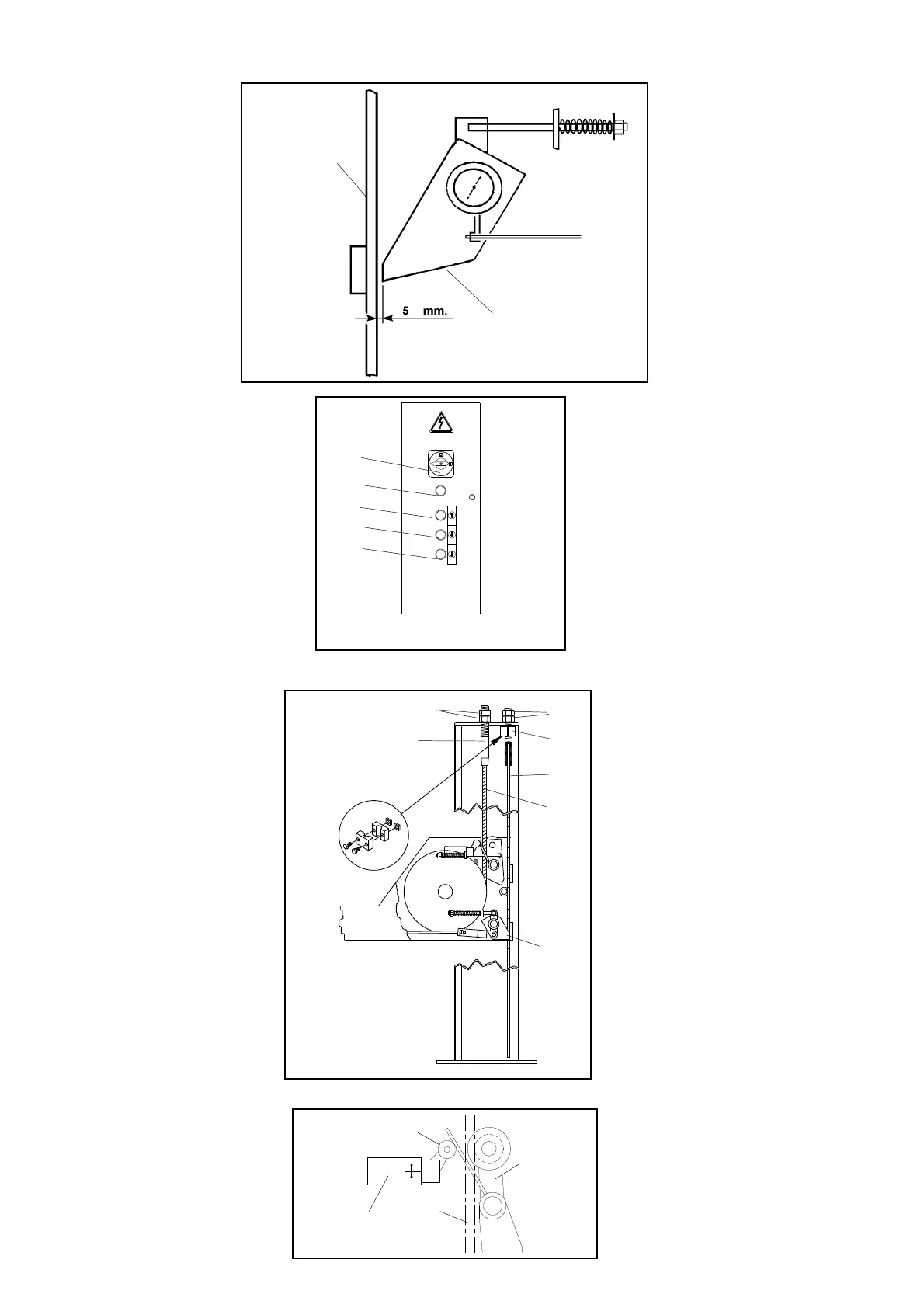
3)laregolareaperturadeimar
-
telletti.Tenendopremutoilpul
-
santedidiscesaverificarechela
distanzatralasicurezzael’asta
siadi5mmfig.49unadistanza
inferiorepotrebbecausarel’ag
-
gancioaccidentaledellasicurez
-
za,unadistanzasuperioreimpe
-
direbbelaperfettachiusura
dell’elettromagneteoriginando
rumorosevibrazioni.
PREREGISTRAZIONIFUNI
Primadimettereinfunzioneilsollevatorecon
-
trollarechelefunisianoinposizionecorretta
sullepulegge.
Chiudereilquadro,portarel’interruttore(QS)
inpos.1efarsalireilsollevatorefinoalibera
-
reicavalletti(A-B-C-D),riportarel’interruttore
inpos.0quinditoglierli.
Portarel’interruttoregenerale(QSinFig.50)in
posizione1,premereilpulsantedidiscesa
(SB2)everificarecheilsollevatorescenda.
Secio’nonavvenisseverificarelaregolazione
dei4sensorifuni(pos.17,Fig.45)e,seneces-
sario,regolarliagendosullavitedellalevadi
scattodelmicrointerruttore(pos.36,Fig.50).
Fig.50 Pannello di controllo
Posizionareilsollevatoreinmodochei
4martelletti(32),mostratiinFig.51,sia-
noalloggiatidentroleasoledelleastedi
sicurezza(12).Agendosuidadi(20)dei
terminali(19)dellefuni(33)eseguirele
registrazionidellepedane(7e8)in
mododaottenerelaplanaritàdituttala
partemobile.
Agendosuidadisuperiori(35)delleaste
disicurezza,regolarleinmododaavere
un’egualedistanzatraimartelletti(32)e
leasoledelleastedisicurezza(12)sulle
4colonne(1-2-3-4).Bloccarelaparte
superioreconcontrodado(35).
Bloccareleastedisicurezza(12)conil
collare(34)fissandolosottolapiastra
superioredellacolonna.
ATTENZIONE: Registrarelefunicon
chiavedinamometricaecontrollareche
abbianotuttelastessacoppiadiserrag
-
gio.
Fig.51 Preregistrazione funi
Fig.52
Beforemakinganymanoeuvres:
1)Checkthefluidlevel,andfillifnecessaryusingmineraloilfor
hydraulicsystem
ISO32-H-LPDIN51525
2)Checktherotationdirectionof
themotorbypushingthelifting
pushbuttonmomentarily
WARNING:prolongedrotationin
thewrongdirectioncanseriously
damagethepump.
3)adjusttheopeningofthewed
-
ges.Keepingthedescentbutton
pressed,checkthedistance
betweenthesafetydeviceand
therodis5mm.Alesserspace
couldcausethesafetydevice
hooking,whileagreaterspace
couldpreventaperfectelectro
-
magnetclosurewithconsequent
noisyvibration.
CABLEPRE-ADJUSTMENT
Beforeoperatingwiththeliftercheckthatthe
cablesareincorrectpositiononthepulleys.
Closethepanel,puttheswitch(QS)inpos.1
andmaketheliftriseuntilclearingthewedges
(A-B-C-D);thenputtheswitchinposition0and
closethemagain.Putthemainswitch(QSin
fig.49)inposition1,presstheloweringbutton
(SB1)andcheckiftheliftlowers.Ifthisdoesn’t
happen,checktheadjustmentofthe fourcable
sensors(pos.17,fig.45)and,ifnecessary,ad
-
juststthembyacting onthescrewofthe micro
switchreleaselever(pos.36,fig.50).
Fig-50Controlpanel
Positiontheliftsothatthefourwedges
(32)infig.51arefirmlyseatedintheslots
onthesafetyrods(12).Adjustthenuts
(20)ontheterminalblocks(19)ofthelift
cables(33)toleveltheplatforms(7and8)
sothattheentiresurfaceofthemovable
sectionoftheliftisperfectlylevel.
Turntheuppernuts(35)oftherods,adjust
sothatthedistancebetweenthewedges
(32)andtheslotsinthesafetyrods(12)is
identicalonallfourposts(1-2-3-4).Tig
-
htentheupperpartwiththelocknut(35).
lockthesafetyrods(12)withthecollar
(34)fixingitunderthetopplateofthecu
-
lomn.
WARNING:Adjustthecableswithatorque
spannerandcheckthatallhavethesame
torquesetting.
Fig.51Pre-adjustmentofliftcables
30
Martelletto
Wedge
Astadisicurezza
Safetyrod
Fig.49
QS
SB2
SB1
SB3
SB8
Fune
Rope
Sensore
Sensor
Microinterruttore
Microswitch
36
20
19
32
12
35
33
34
34
 Loading...