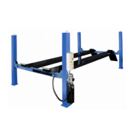
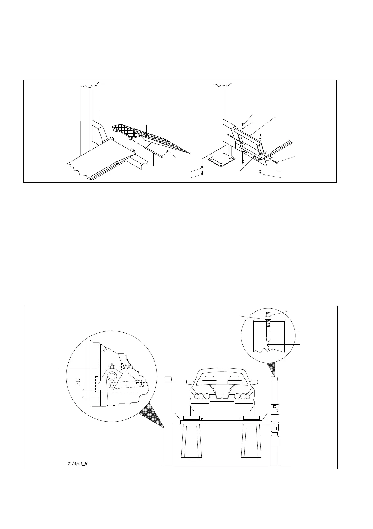
MONTAGGIORAMPEDISALITAEARRESTIFERMARUOTA
Lerampedisalita(pos.41,Fig.56)egliarrestifermaruota(42)pos
-
sonoesseremontatidaambolepartidellepedane(7-8)secondo
lenecessitàdell’utilizzatore.Procederealmontaggioincastrando
sullatodesideratolerampedisalita(41)efissaretramiteviti(43e
48),lerosette(44)eidadi(45e49)gliarrestifermaruota(42)sul
latoopposto.
Serichiestomontarelevitidiregolazioneperlaposizioneaterra
(50e51).
Fig.56 Fissaggiorampeebloccaggiruote
REGISTRAZIONEFUNI
Fig.57:saliresulponteconun’autovettura.
Posizionarsiall’altezzamassimaeverificarechei4martel-letti
(32)sianoalloggiatidentroleasoledelleastedisicurezza(12).
Verificarecheladistanzatraimartelletti(32)eleasoledelleaste
disicurezza(12)sulle4colonne(1-2-3-4)sia20mmminimodal
suoappoggio(fig.57)unamisurainferiorenondarebbeiltempo
allasicurezzariruotarerimanendoagganciataall’asta.
Senecessarioprocedereallivellamentoagendosuidadi(20)dei
terminali(19)dellefuni(33)eregolandoilmicrointerruttorefinecor-
sa.
Aregistrazioneultimatabloccareconicontrodadi(35).
IMPORTANTE:Questaoperazionediregistrazioneédaripe-
ter-sidopo1o2settimanedallamessainserviziodelsolleva
-
tore.
Fig.57 Registrazionefuni
INSTALLINGTHEVEHICLERAMPSANDTHEWHEELSTOPS
Thevehicleramps(pos.41,fig.56)andthewheelstops(42)canbe
fittedoneitherendofplatforms(7-8)accordingtotheuser’sre
-
quirements.Fittheramps(41)byslottingthemintotheplatforms
ontherequiredendandthenfixthewheelstops(42)ontheoppo
-
siteendusingscrews(43and48),thewashers(44),andthenuts
(45and49).
Ifrequeredfittheregulationscrewsforgroundpositionament(50
and51).
Fig.56 Securing the vehicle ramps and wheel stops
ADJUSTINGTHELIFTCABLES
Fig.57:driveavehicleontothelift.
Raisethelifttothemaximumheightandcheckifthefourwedges
(32)arefittedinsidetheslotsofthesafetyrods(12).
Checkifthedistancebetweenthewedges(32)andtheslotsofthe
safetyrods(12)onthe4posts(1-2-3-4)isatleast20mmfromthe
support(fig.57);alowervaluewouldnotallowthesafetydevi
-
cetorotate,anditwouldstayattachedtotherod.
Ifnecessary,leveltheunitbyadjustingthenuts(20)onthe
terminals(19)ofthecables(33)andthelimitmicroswitch.
Whentheadjustmentiscompleted,lockwiththelocknuts(35).
IMPORTANT:Thisadjustmentmustberepeated1or2weeks
aftersettingupthelift.
Fig.57 Adjusting the lift cables
32
12
32
20
35
19
33
41
47
46
51
43
44
44
42
45
50
48
49