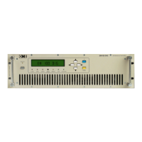
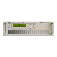
FM TRANSMITTER
TR EM 1000 HE DIG PLUS COMPACT
Technical Manual 1v2 November 2019 17
• The power supply nominal range comes from 100-265VAC (nominal voltage single-phase
230VAC).
• Mains fluctuations and electrical discharges due to weather or nearby industrial machinery
may cause significant trouble, especially in mountain areas and in locations close to industrial
areas.
• In such cases, it is advisable, if not indispensable, to install a protector, an insulating
transformer, or possibly an electromechanical mains voltage regulator.
• Even though the mains regulator allows for a wide incoming voltage range, it is important to
avoid operating using high impedance mains lines in proximity to the lowest permitted AC
limit: if the line falls below a given value while fully loaded, the control circuit for the lowest
AC limit may trigger a very dangerous oscillating on/off cycle. In such cases, we recommend
using a stabilizer on the external line.
1.4.4 Wiring the device
This section describes the minimum connections required to place the transmitter in
operation.
- Wiring into the antenna
Connect the RF OUT connector to the antenna or to the next RF amplifier via a high-quality 50
Ohm shielded coaxial cable equipped with the appropriate connectors.
It is indispensable that only low-loss cables be used when connecting directly to the antenna:
in such cases, Celflex or another similar ½" cable is recommended. Larger cables must be
connected using flexible terminal ends from the smallest section, in order to avoid mechanical
stress on the output connector.
It is very important to ensure that the antenna, cables, and connectors have the correct
impedance and are appropriate to the transmitter’s nominal power level.
The antenna must be suitable for FM broadcasting and able to resonate at the operating
frequency with the minimum possible SWR.
The antenna must be grounded via a copper braid of suitable cross-section to prevent
lightening or static electricity from reaching the amplifier through the antenna cable.
- Connection to modulation signals
Connect the LEFT and RIGHT modulation inputs, or the MPX input alternatively, based on
your desired operating mode (monophonic or stereophonic) and the type of source being
used (mono, stereo, or multiplex signal).
The MPX connector is internally connected in parallel to the RIGHT connector. As such, if
the MPX connector is in use, the simultaneous connection of signals to the LEFT and RIGHT
connectors is not possible. Again in this case, the highest impedance position is 5KOhm.
- Wiring into the mains
1) Verify that the rear power switch is turned off; if it is not off, do so now.
2) Ground the system.


 To Next Page