FM TRANSMITTER
TR EM 1000 HE DIG PLUS COMPACT
Technical Manual 1v2 November 2019 18
3) According to your model, connect the power cable or the device’s cable to a suitable single-
phase input (230VAC nominal voltage).
Before connecting the power, ensure that it is appropriate and is able to support the
consumption required by the transmitter model you intend to use.
Your transmitter should not be used when near the lower voltage limit with high-
impedance lines: if the line voltage falls below a certain limit at full load, the low voltage
sensor circuit could trigger a continuous, extremely dangerous on/off cycle. In such case,
install an external voltage stabilizer.
In order to ensure proper operation and comply with safety regulations, proper grounding is
required. Use the yellow/green lead in the power cable. The cable neutral lead is blue.
Never connect the earth to the mains neutral lead.
Use only the power supply cable supplied with the transmitter. For cable extensions,
sections of sufficient and appropriate length are recommended.
Never turn the device on without an antenna connection, even when in stand-by.
- Connection to the auxiliary modulation (optional)
Where necessary, an auxiliary RDS or SCA modulation source can be connected to the AUX
input.
- Parallel port for remote control (optional)
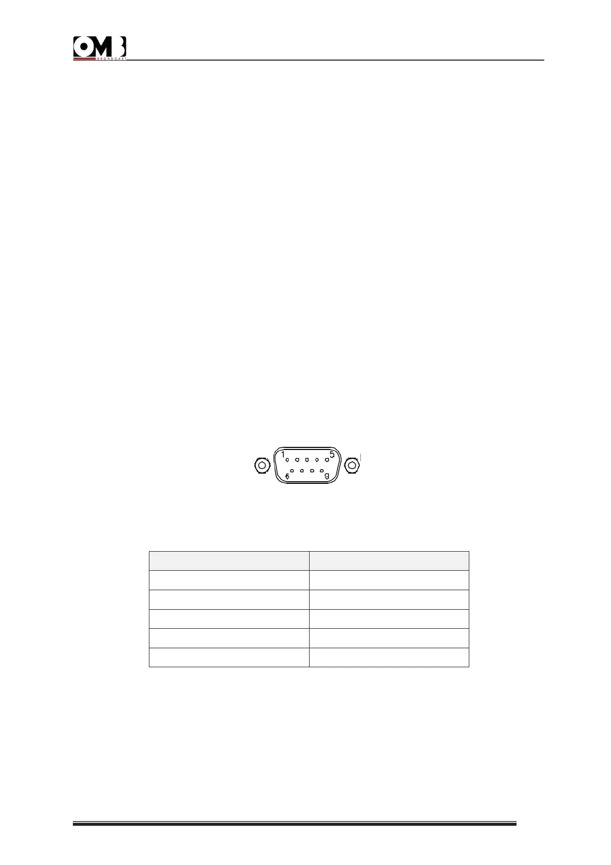
Where necessary, connections can be made to the REMOTE parallel port. Various lines are
located in this port for simple, direct control of the transmitter via a male DB9 connector.
Connection of the pins is outlined in the following table:
- Connection to the RS232 port (optional)
Where necessary, connections can be made to the RS232 port. This port manages Tx, Rx, and
related return data signals via a RS232 standard without any “handshake” signal.
The above signals are inversely connected to the port; as such, a simple pin-to-pin type serial
cable is sufficient, directly connected to suitable connectors, usually a female DB9 or DB25 on


 To Next Page