FM TRANSMITTER
TR EM 1000 HE DIG PLUS COMPACT
Technical Manual 1v2 November 2019 81
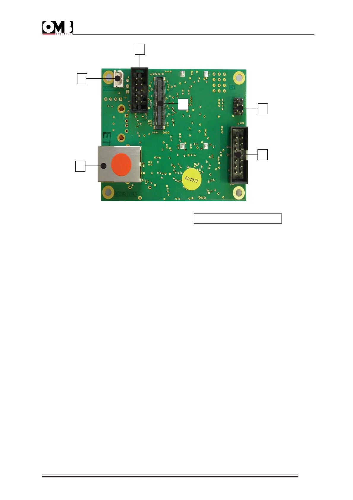
[1] LAN: the flashing green LED indicates that the board is powered and functioning. The
flashing speed increases when the software is updated.
[2] DATA: the flashing green LED indicates normal communication with the CPU system.
[3] GSM LED: green, related to GSM.
[4] GSM LED: green, related to GSM.
[5] LAN port: RJ45(F) Ethernet network connector. It can be mounted directly on the rear
panel of the device or can be connected with an ETHERNET cable and an RJ54
connection panel.
[6] BATTERY CONNECTOR: used to connect the lithium-ion battery. It is used only if the
GSM modem is installed.
[7] DATA TRANSFER RS485: 10-pin connector for connection to the card (optional).
[8] PROGRAMMING PIN (reserved for the factory): connector to load the uCU firmware.
[9] 4-pin connector: for connection to a central control card.
[10] 80-pin connector: for modem connection: TELIT GE864-QUH V2 / GPS QUAD.BAND
GSM MODEM.
Ethernet BOARD, connector
 Loading...