35
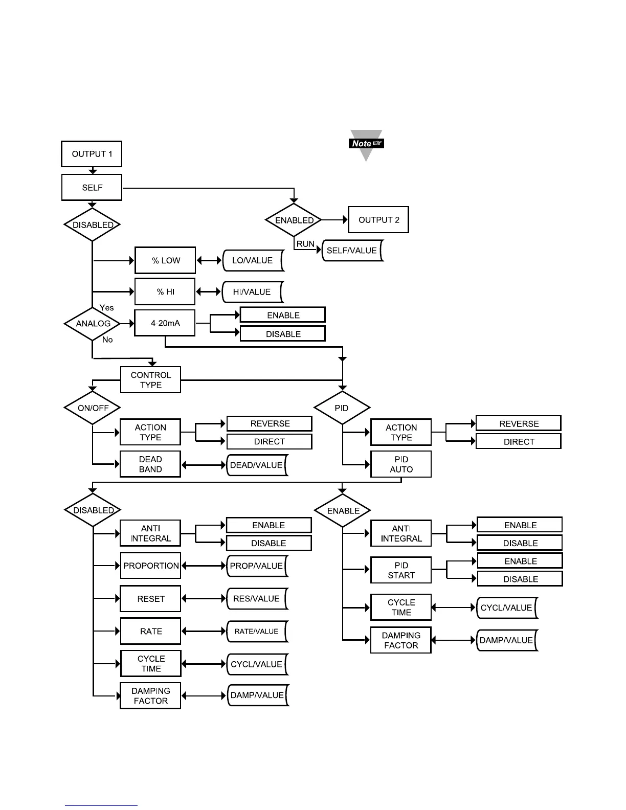
3.2.10 Output 1
Alarm 1 and Output 1 or Analog Output (Retransmission) share the same contacts
on the rear panel connector. If Alarm 1 or Analog Output (Retransmission) is
Enabled, Output 1 is automatically Disabled.
Figure 3.9 Flow Chart for Output 1
It is required that you put
the controller in the
Standby Mode for any
configuration change other
than Set Points & Alarms.
 Loading...