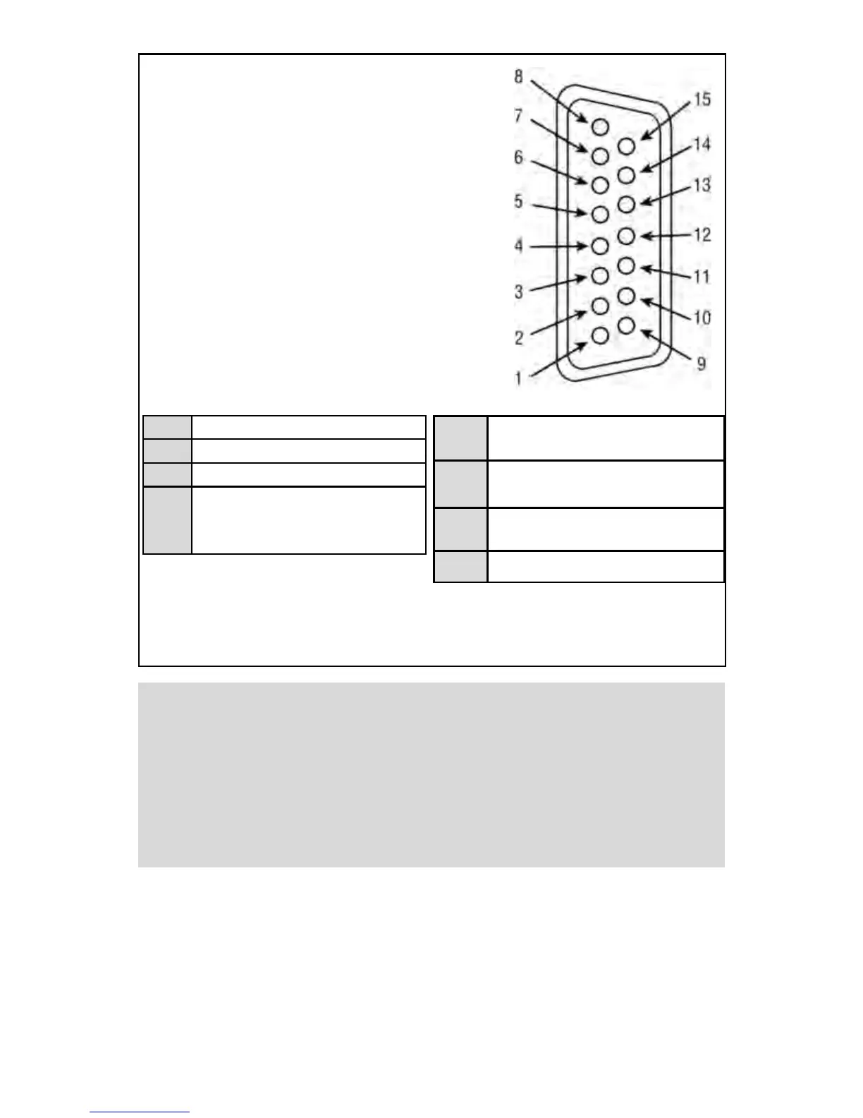
4
PIN FUNCTION
1 0 to 5 VDC Flow Signal Common
2 0 to 5 VDC Flow Signal Output
3 Common
4 Open (Purge)
5 Common, Power Supply
6 (unassigned)
7 +12 VDC (Optional +24 VDC*) Power Supply
8 Remote Setpoint Input
9 4 to 20 mA (-) Flow Signal Return (use with 14)
10 Remote Setpoint Common (use with 8)
11 +5VDC Reference Output for Remote Setpoint
12 Valve Off Control
13 Auxiliary +12 VDC (Optional +24 VDC*)
Power Output (For Loads <100 mA)
14 4 to 20 mA (+) Flow Signal Output
15 Chassis Ground
FIGURE 2-1 FMA 5400A/5500A 15-PIN “D” CONNECTOR CONFIGURATION
*Do not connect +24 Vdc power supply unless your FMA 5400A/5500A controller was
ordered and configured for 24 Vdc
1 & 2 0-5 Vdc OUTPUT
3 & 4 PURGE
3 & 12 VALVE OFF CONTROL
5 & 13
AUXILIARY +12 Vdc (Optional +24
Vdc*) POWER OUTPUT (FOR LOADS
<100 mA)
CAUTION: BEFORE CONNECTING THE POWER SUPPLY CHECK
YOUR CONTROLLER MODEL NUMBER AND POWER SUPPLY
REQUIREMENTS LABEL LOCATED ON THE CONTROLLER BACK
COVER. DO NOT CONNECT 24 Vdc POWER SUPPLY UNLESS
YOUR FMA 5400A/5500A CONTROLLER WAS ORDERED AND
CONFIGURED FOR 24 Vdc. EXCEEDING THE SPECIFIED
MAXIMUM POWER SUPPLY VOLTAGE LIMIT MAY RESULT IN
PERMANENT DEVICE DAMAGE.
Important notes:
In general, “D” Connector numbering patterns are standardized. There are, how-
ever, some connectors with nonconforming patterns and the numbering
sequence on your mating connector may or may not coincide with the numbering
sequence shown in our pin configuration table above. It is imperative that you
match the appropriate wires in accordance with the correct sequence regardless
of the particular numbers displayed on your mating connector.
5 & 7
+12 Vdc (Optional +24 Vdc*) POWER
SUPPLY
8 & 10
0-5 Vdc OR 4-20 mA (FROM 3 WIRE LOOP
SOURCING DEVICE) REMOTE SETPOINT
9 & 14
4-20 mA OUTPUT (SOURCING, ONLY
FOR PASSIVE LOAD)
10 & 11 +5 Vdc CONTROL SOURCE