5
Power must be turned OFF when connecting or disconnecting any cables in the system.
The power input is protected by a 900mA (FMA 5400/5500 Series Max. Flow 10,
50, 100 L/min) or 1600mA (FMA 5400A/5500A Series Max. Flow 200, 500 and
1000 L/min) M (medium time-lag) resettable fuse. If a shorting condition or polari-
ty reversal occurs, the fuse will cut power to the flow transducer circuit. Disconnect
the power to the unit, remove the faulty condition, and reconnect the power. The fuse
will reset once the faculty condition has been removed.
Use of the FMA 5400A/5500A flow transducer in a manner other than that specified in this
manual or in writing from OMEGA
®
, may impair the protection provided by the equipment.
CAUTION: Fuse will not protect controller if power supply voltage
exceeds maximum voltage specified for a particular model.
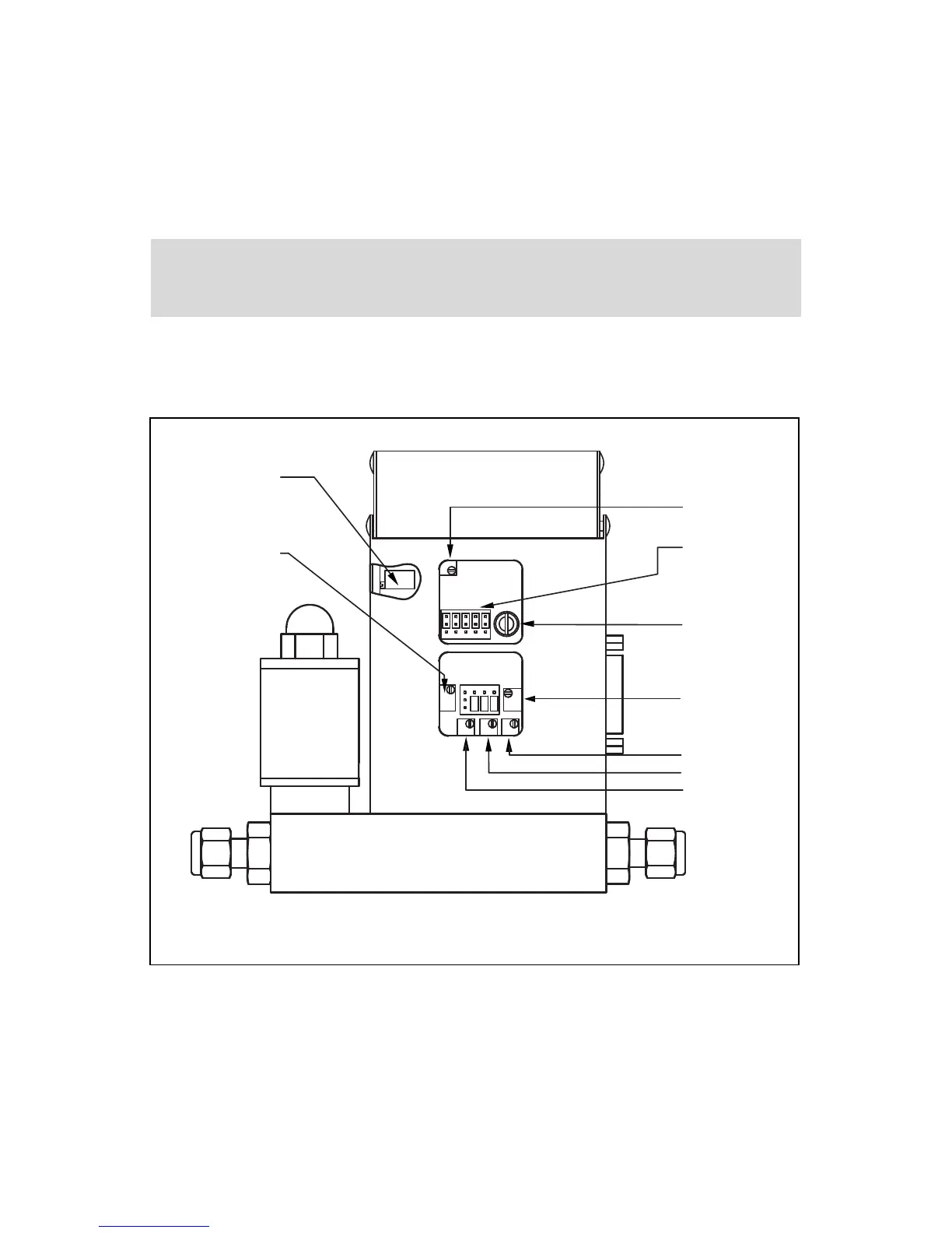
FIGURE 2-2, POTENTIOMETER AND JUMPER LOCATIONS
2.2.1 Valve Control Configuration
There are three basic valve control options.
(a) LOCAL or REMOTE control.
(b) 0 to 5 VDC or 4 to 20 mA setpoint signal -
*Note: this only applies for the REMOTE control configuration;
(c) 2% cutoff active or not active. Note: 2% cutoff not available for FMA 200, 500 and
1000 L/min.