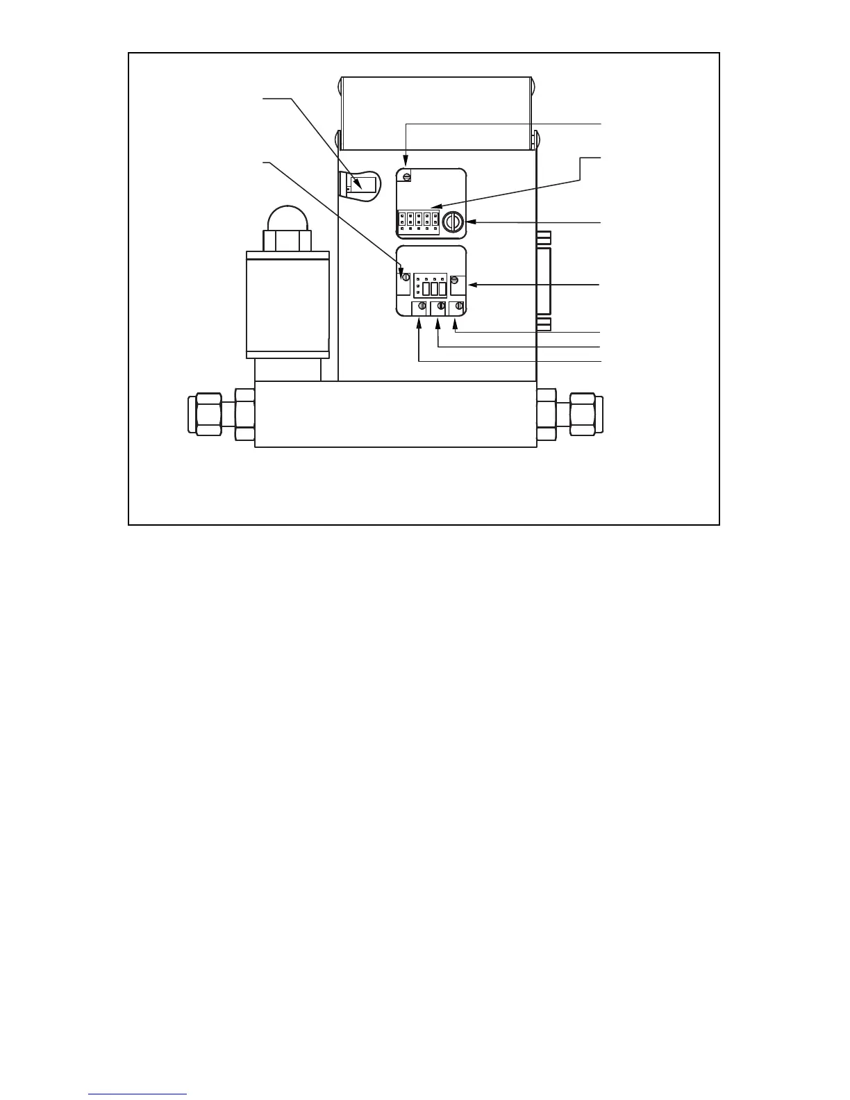
FIGURE 7-1 FMA 5400A/5500A SERIES MAX. FLOW 10, 50, 100 L/MIN CALIBRATION
POTENTIOMETER AND JUMPER LOCATIONS (BACK OF FMA 5400A/5500A )
7.2 Calibration of FMA 5400A/5500A Series Max.
Flow 10, 50, 100 L/min Mass Flow Controllers
All adjustments in this section are made from the outside of the meter, there is no
need to disassemble any part of the instrument.
FMA 5400A/5500A Mass Flow Controllers may be field recalibrated/checked for
the same range they were originally factory calibrated for. When linearity adjust-
ment is needed, or flow range changes are being made proceed to step 7.2.4.
Flow range changes may require a different Restrictor Flow Element (RFE).
Additionally, a different Solenoid Valve Orifice may also be required (see Table VI).
Consult OMEGA
®
for more information.
7.2.1 Connections and Initial Warm Up
At the 15-pin “D” connector of the FMA 5400A/5500A transducer, connect the
multimeter to output pins [1] and [2] for 0 to 5 VDC (or pins [9] and [14] for 4 to 20
mA) - (see Figure 2-1).
When using a remote setpoint for flow control, the appropriate reference signal
should also be connected to the 15-pin “D” connector at pins [8] and [10] - (see
Figure 2-1). Power up the Mass Flow Controller for at least 30 minutes prior to
commencing the calibration procedure.
19