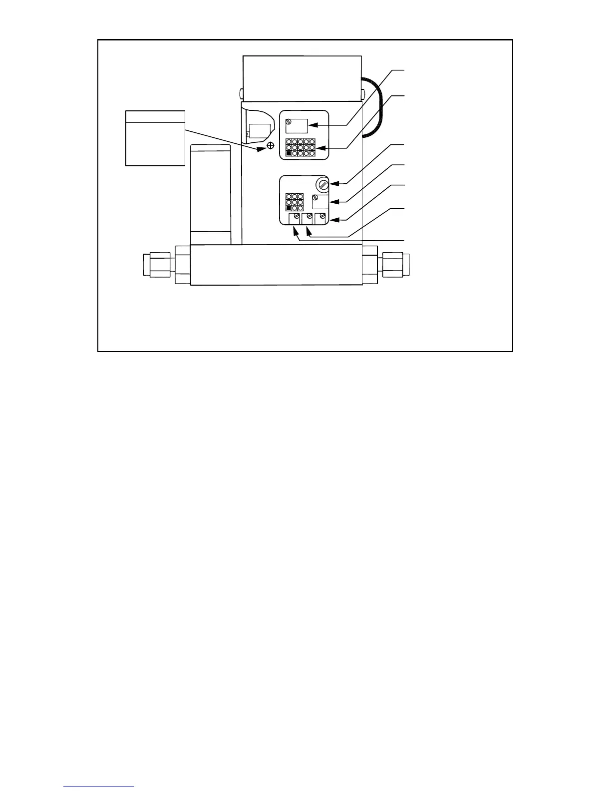
FIGURE 7-3 FMA 5400A/5500A SERIES MAX. FLOW 200, 500 AND 1000 L/MIN
CALIBRATION POTENTIOMETER AND JUMPER LOCATIONS (BACK OF FMA 5400A/5500A)
7.3.1 Connections and Initial Warm Up
At the 15-pin “D” connector of the FMA 5400A/5500A transducer, connect the
multimeter to output pins [1] and [2] for 0 to 5 Vdc (or pins [9] and [14] for 4 to 20
mA) - (see Figure 2-1). When using a remote setpoint for flow control, the appro-
priate reference signal should also be connected to the 15-pin “D” connector at
pins [8] and [10] - (see Figure 2-1). Power up the Mass Flow Controller for at least
30 minutes prior to commencing the calibration procedure.
7.3.2 ZERO Adjustment
Shut off the flow of gas into the Mass Flow Controller. To ensure that no seepage
or leak occurs into the meter, temporarily disconnect the gas source. Using the
multimeter and the insulated screwdriver, adjust the ZERO potentiometer [R34]
through the access window for 0 Vdc (or 4 mA respectively) at zero flow.
7.3.3 SPAN Adjustment
Reconnect the gas source. Adjust the control setpoint to 100% of full scale flow.
Check the flow rate indicated against the flow calibrator. If the deviation is less
than ±10% of full scale reading, correct the SPAN potentiometer [R33] setting by
using the insulated screwdriver through the access window, to eliminate any devi-
ation. If the deviation is larger than ±10% of full scale reading, a defective condi-
tion may be present.