7.2.18 Close Loop 50% Flow Adjustment
Change the setpoint to 2.50 VDC to control at 50% of full scale flow. Check the
flow rate indicated against the flow calibrator. If the flow is not within ±0.75% of
full scale, re-adjust the setting for potentiometer [R38], until the flow output is cor-
rect.
7.2.19 Close Loop 75% Flow Adjustment
Change the setpoint to 3.75 VDC to control at 75% of full scale flow. Check the
flow rate indicated against the flow calibrator. If the flow is not within ±0.75% of
full scale, re-adjust the setting for potentiometer [R39], until the flow output is cor-
rect.
7.2.20 Close Loop 100% Flow Adjustment
Change the setpoint to 5.00 VDC to control at 100% of full scale flow. Check the
flow rate indicated against the flow calibrator. If the flow rate is not within ±0.75%
of full scale, re-adjust the setting for potentiometer [R40], until the flow output is
correct.
Repeat steps 7.2.15 to 7.2.20 at least once more.
24
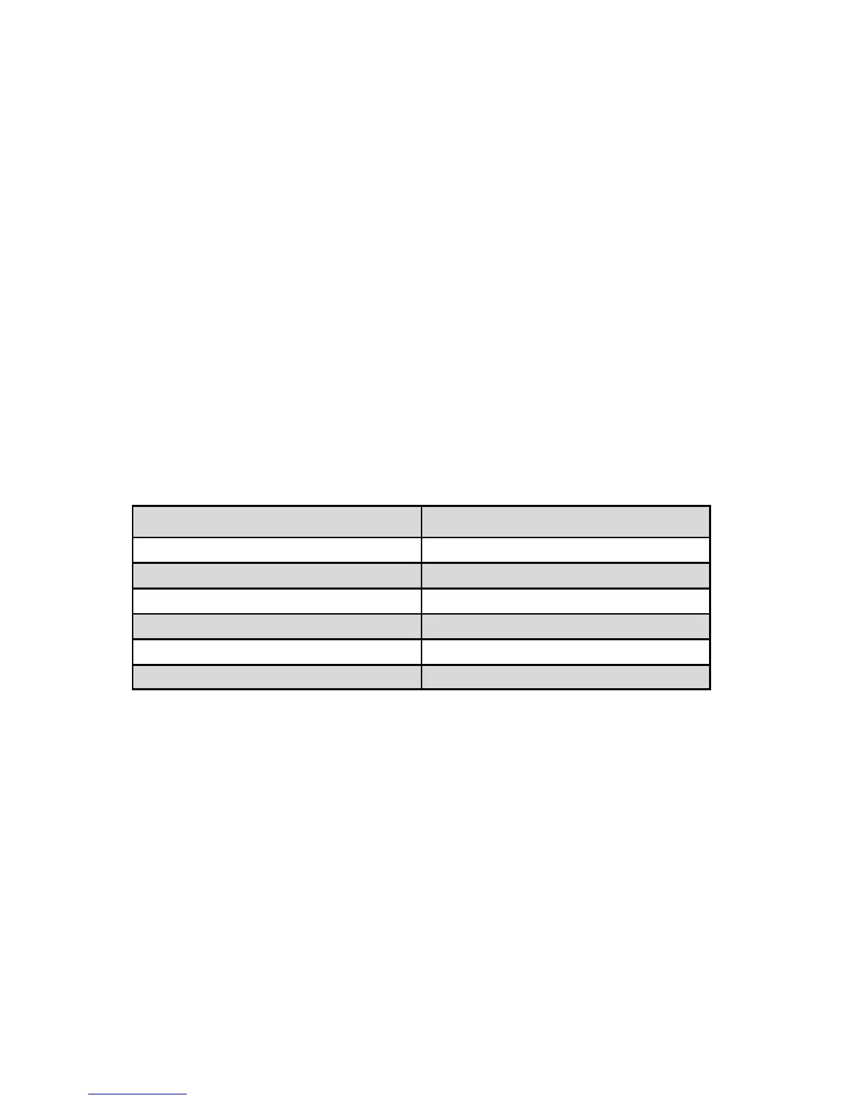
ORIFICE PART NUMBER FLOW RATE [N
2
]
OR.020 10 to 1000 sccm
OR.040 1 to 5 slpm
OR.055 5 to 10 slpm
OR.063 10 to 15 slpm
OR.094 20 to 50 slpm
OR.125 50 to 100 slpm
TABLE II FMA 5400A/5500A SOLENOID VALVE ORIFICE SELECTION TABLE
7.3 Calibration of FMA 5400A/5500A Series Max.
Flow 200, 500 and 1000 L/min
Mass Flow Controllers
All adjustments in this section are made from the outside of the meter, there is no
need to disassemble any part of the instrument. FMA 5400A/5500A Mass Flow
Controllers may be field recalibrated/checked for the same range they were orig-
inally factory calibrated for. When linearity adjustment is needed, or flow range
changes are being made proceed to step 7.2.4. Flow range changes may require
a different Restrictor Flow Element (RFE). Additionally, a different Solenoid Valve
Orifice may also be required (see Table VI). Consult Omega
®
for more information.