6 Device overview
Bode 100 is a USB controlled vector network analyzer. The system consists of the Bode 100 hardware
and the Bode Analyzer Suite software. In the following the Bode 100 hardware is described in detail.
To learn more about the Bode Analyzer Suite, please check out 7.4 Performing your first measurement
on page 18 ff.
6.1
Connectors
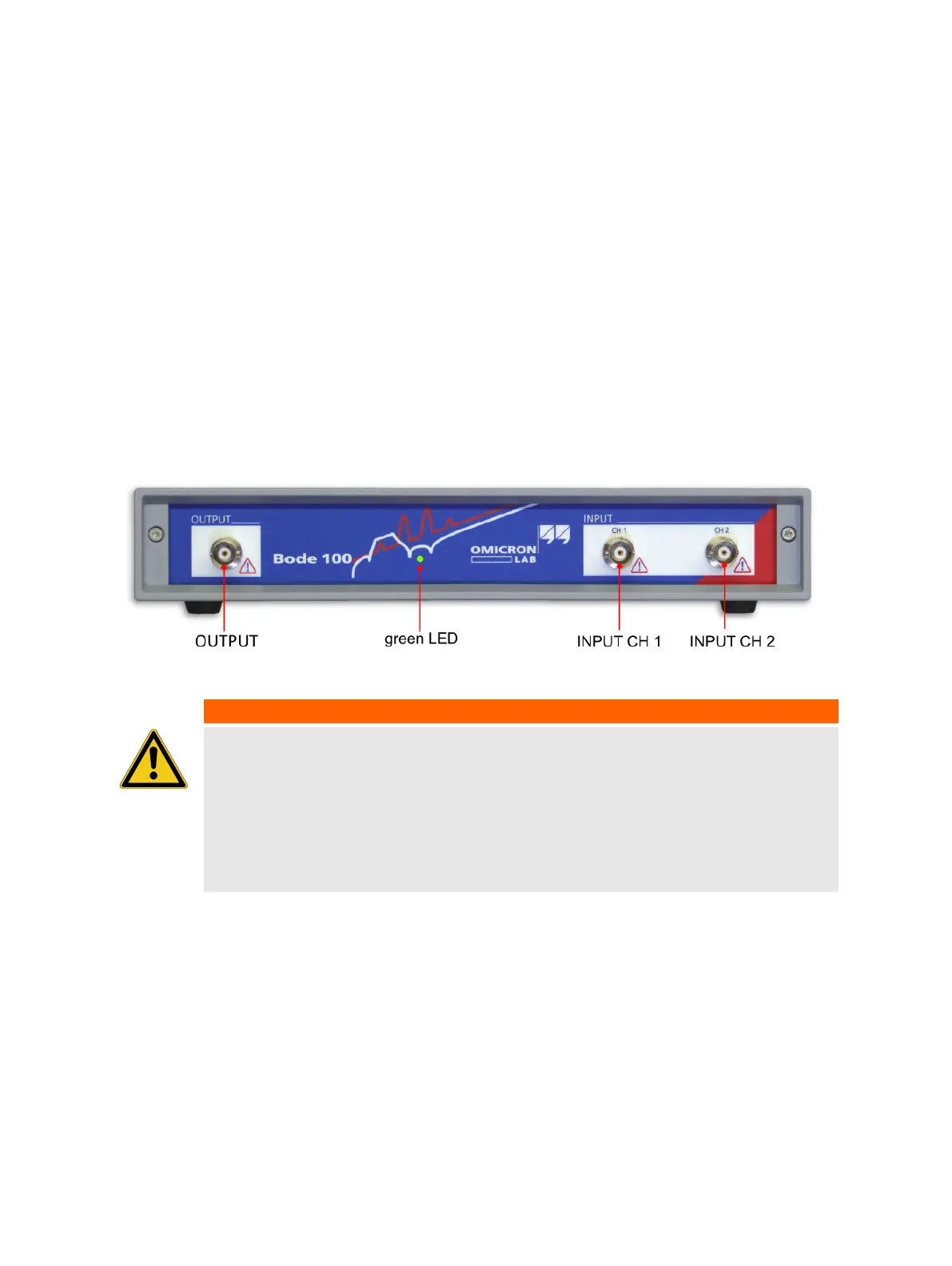
Bode 100 provides the following three connectors at the front panel:
• OUTPUT: signal output (BNC socket)
• CH 1: channel 1 signal input (BNC socket)
• CH 2: channel 2 signal input (BNC socket)
Figure 6-1: Bode 100 front view
WARNING
Death or severe injury can occur if hazardous voltages are connected to the
Bode 100.
Bode 100 is a SELV device (SELV = Safety Extra Low Voltage according to IEC
60950-1).
► Do not apply voltage levels >50 VDC or >25 VAC to the inputs of Bode 100.
► Be aware that no indication on Bode 100 shows that the output is active. This
could be especially critical if amplifiers are connected to Bode 100.
Device overview
OMICRON Lab
15

 Loading...


