22
Explanation of the block diagram
1) 3-phase electronic switch :
Used to select system I or II.
The switch is controlled by the sliding switch at the rear panel of the
CMA 56, where system I corresponds to the voltage system and system
II corresponds to the current system of the CMC test device.
2) Isolation amplifier for isolation between the inputs and outputs (CMA 56
is isolated from the CMC test device and mains).
3) Signal processing block (filter, offset correction,...)
4) 3-phase current amplifier
5) Monitoring facilities:
Hardware test upon switching the device ON.
Temperature monitoring
Operating state display
Communication interface for the CMC test device
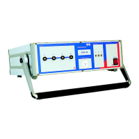
6) LEDs on the front panel for displaying the operating state
 Loading...