ENGLISH
• 3 •
thewaterowisinthedirectionmarkedonthecap.(E) Useintegral
bracketcapasatemplatetomarkscrewlocationsonwall.Insert
mountingscrewsintowall.Leaveaspacebetweentheheadofthe
screwandthewalltoslipbracketontoscrews.
NOTE:Allow1
1
⁄2-inchesclearancebelowhousingtoenablelter
cartridgechanges.
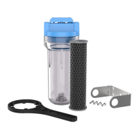
3. (F) Assembleallttings.Startadaptersintocapbyhand.Usea
wrenchtotightenrmly.DO NOT OVER-TIGHTEN.
(G) Removecompressionnutsfromttings.
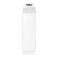
4. (H) Measurelengthacrossassembledttingsandsubtract1-inchfor
3/4-inchpipeor1
1
⁄2-inchesfor1/2-inchpipe.Marksectionofpipeto
beremoved.
NOTE:Approximately6-incheswillberemovedfor3/4-inchpipe.
(I) Usingapipecutterorhacksaw,cutpipeandremovemarked
section.Fileorsandsharpedgesonremainingpipe.
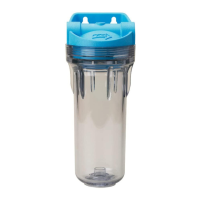
5. (J) Slipabrasscompressionnutand(K) abrassferruleontoeachend
of3/4-inchpipe.
6. (L) Spreadendsofpipeaparttoinstalllterassembly.Usingtwo
adjustablewrenches,holdinletadaptersecurelywithonewrenchand
tightenwithsecondwrench.Repeatprocessforoutletadapter.
Ifusingmountingbracket,besuretoslipbracketoverscrewsinwall
(seestep2).
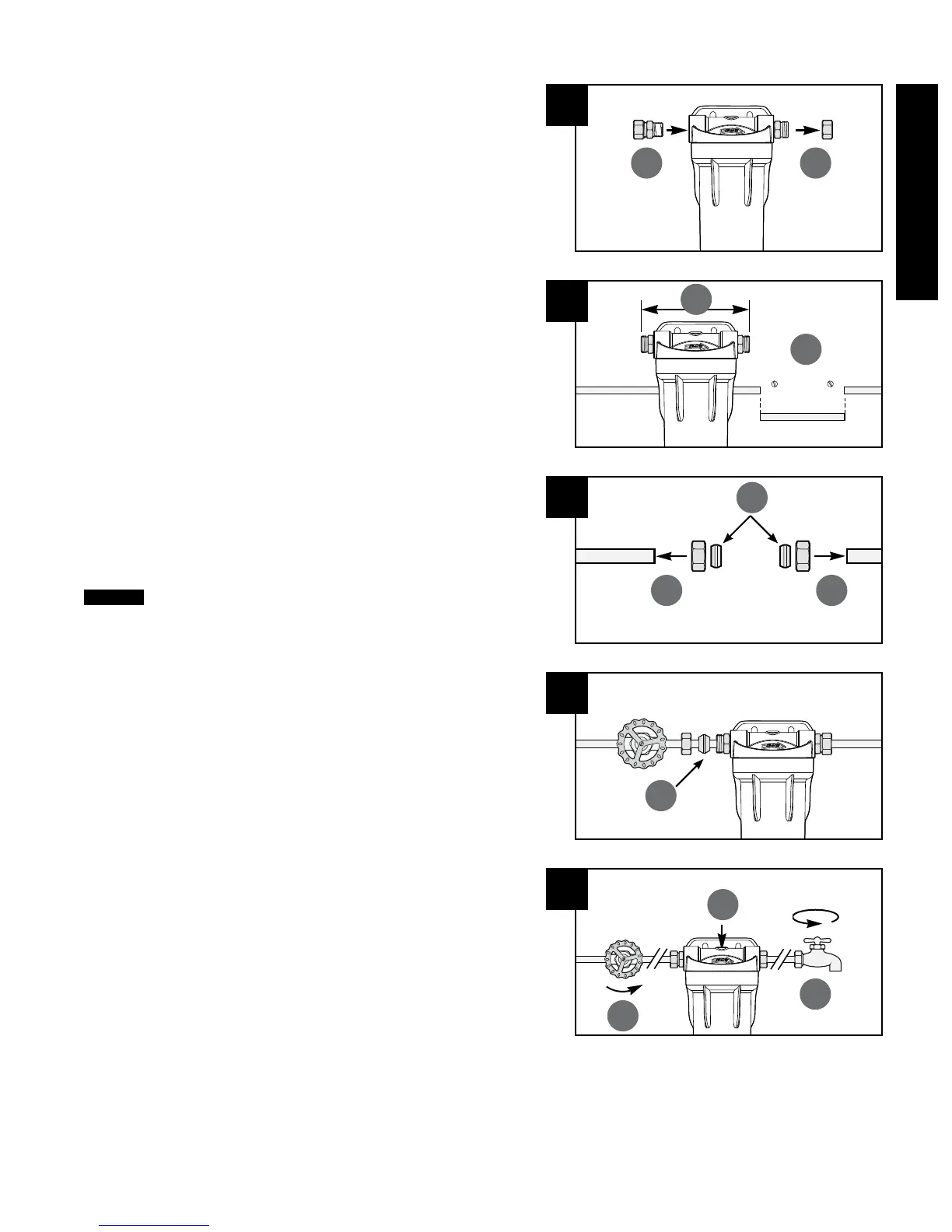
7. (M) Slowlyturnonwatersupplytoallowltertollwithwater,
(N) thendepressredpressure-reliefbuttonontopofcaptorelease
trappedair.Checkforleaksbeforeleavinginstallation.(O) Open
nearestfaucetandushcartridgefor5minutes.
Ifwaterpipesareusedtogroundelectricalsystems,appliances
orphones,becertaintoinstallajumperwire.Contactaqualied
electricianwithanyquestionsaboutyourhome’selectricalsystem.
3
F G
L
6
H
I
4
M
7
N
O
J
5
J
K
 Loading...