•
4
Operating Elements and Connections
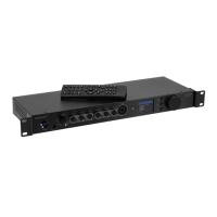
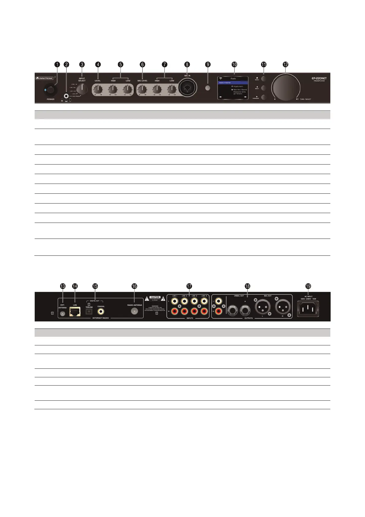
4.1 Front panel
No. Element Function
1 POWER switch
Turns the unit on and off
2 AUX input 3.5 mm jack to connect audio devices with line level; when this jack is
connected, the radio will be muted
3 INPUT select switch
To select the signal source (LINE 1/2/3/4 or AUX/RADIO)
4 LEVEL control
Adjusts the overall volume
5 LOW & HIGH sound controls
Adjust the low and high frequencies for the output signal
6 MIC LEVEL control
Adjusts the microphone volume
7 LOW & HIGH sound controls
Adjust the low and high frequencies for the microphone signal
8 MIC IN input
Connector for microphone (combination XLR/6.3 mm jack)
9 IR sensor
Sensor for remote control
10
Display 2‘‘ TFT display
11 Navigation buttons MENU sets operation mode, BACK ◄ and FORWARD ► select menu
items and settings
12 TUNE/SELECT control
Rotate to select options and to set the radio volume
Press to confirm settings
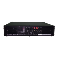
4.2 Rear panel
No. Element Function
13 WiFi antenna jack To connect the supplied rod antenna
14 LAN jack (RJ45) To connect a router via a network cable
15 Digital outputs (optical) Toslink and coaxial connector to connect audio devices with digital input;
these outputs carry the signal of the Internet radio
16 Radio antenna jack To connect the supplied wire antenna for DAB/FM reception
17 INPUTS LINE 1-4 jacks Stereo RCA inputs for audio units with live level (e.g. CD player, tuner)
18 OUTPUT jacks Unbalanced (RCA and 6.3 jack) and balanced (XLR) stereo outputs for
connection to units with line level inputs (e.g. active speakers or amplifier
19 Power input Used to plug in the supplied power cable