35
Control circuit
■STO terminal, EDM terminal
STO terminal and EDM terminal used with the STO function. For details on the STO function, refer to
the User's Manual (I620-E1).
Terminal
symbol
Terminal name Description Electrical characteristics
P24S 24V output terminal (for STO
input only)
A DC24V power supply for contact signals dedi-
cated for ST1/ST2 terminals. The common termi-
nal is CMS.
Maximum output current: 100mA
CMS 24V output terminal common
(for STO input only)
A common terminal for DC24V power supply for
contact signals dedicated for ST1/ST2 terminals.
STC Input logic switching terminal A logic switching terminal for STO input.
You can change the input logic changing the con-
necting point of short-circuit line.
When an external power supply is used, remove
the short-circuit line and use this terminal as the
input common for ST1/ST2.
<For sink logic>
Short-circuit line: Connect between
P24S and STC
<For source logic>
Short-circuit line: Connect between
CMS and STC
ST1/ST2 STO input terminals Input terminals of STO. Voltage between ST1 and STC/ST1
and STC
• ON voltage: Min.DC15V
• OFF voltage Max. DC5V
• Maximum allowable voltage DC27V
• Load current 5.8mA (at DC27V)
Internal resistance: 4.7kΩ
ED+ EDM signal output terminal (+) A plus terminal of EDM signal (STO status moni-
toring).
Open collector output
• Between ED+ and ED-
• Voltage drop at ON: 4V or less
• Maximum allowable voltage: 27V
• Maximum allowable current: 50mA
ED- EDM signal output terminal (-) A minus terminal of EDM signal (STO status mon-
itoring).
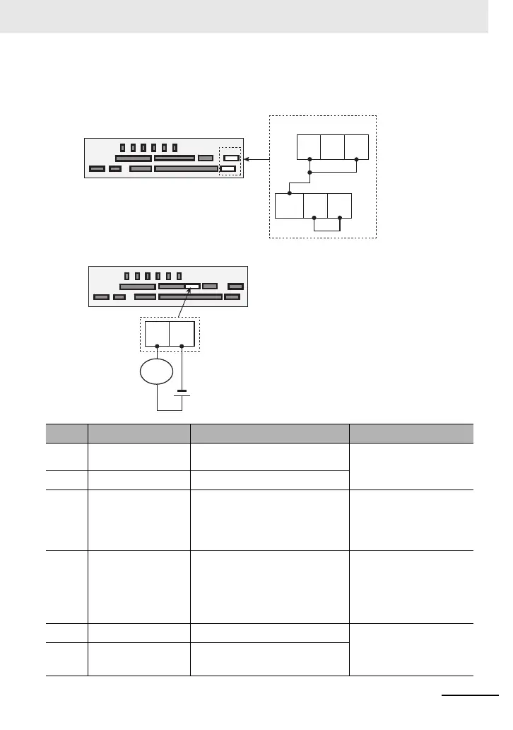
Control circuit terminal area
Wiring condition when shipped.
STO terminal
ST2 STC ST1
P24S STC CMS
Control circuit terminal area
EDM terminal
Wiring example
ED+ ED-
Load
 Loading...


