BU1002SW / BU3002SW
81
7
4. Contact Signal Connector (female DSUB9P)
Front view
Screw size: inch screw
#4-40 UNC
Pin assignment
Pin number
For jumper setting “SC07”
For jumper setting “SC05/06”
* Factory settings
1
Battery LOW signal output (BL)
NC
2
Trouble signal output (TR)
Backup signal output (BU)
3
Backup stop signal input (BS)
Backup reverse signal output (BU)
4
NC
COMMON (COM)
5
COMMON (COM)
Battery Low Signal output (BL)
6
Remote ON/OFF input (–)
Backup stop signal input (BS)
7
Remote ON/OFF input (+)
Remote ON/OFF input (–)
8
Backup signal output (BU)
Trouble Signal output (TR)
9
Battery replacement signal output (WB)
Remote ON/OFF input (+)
BU1002SW
BU3002SW
BU1002SW
BU3002SW
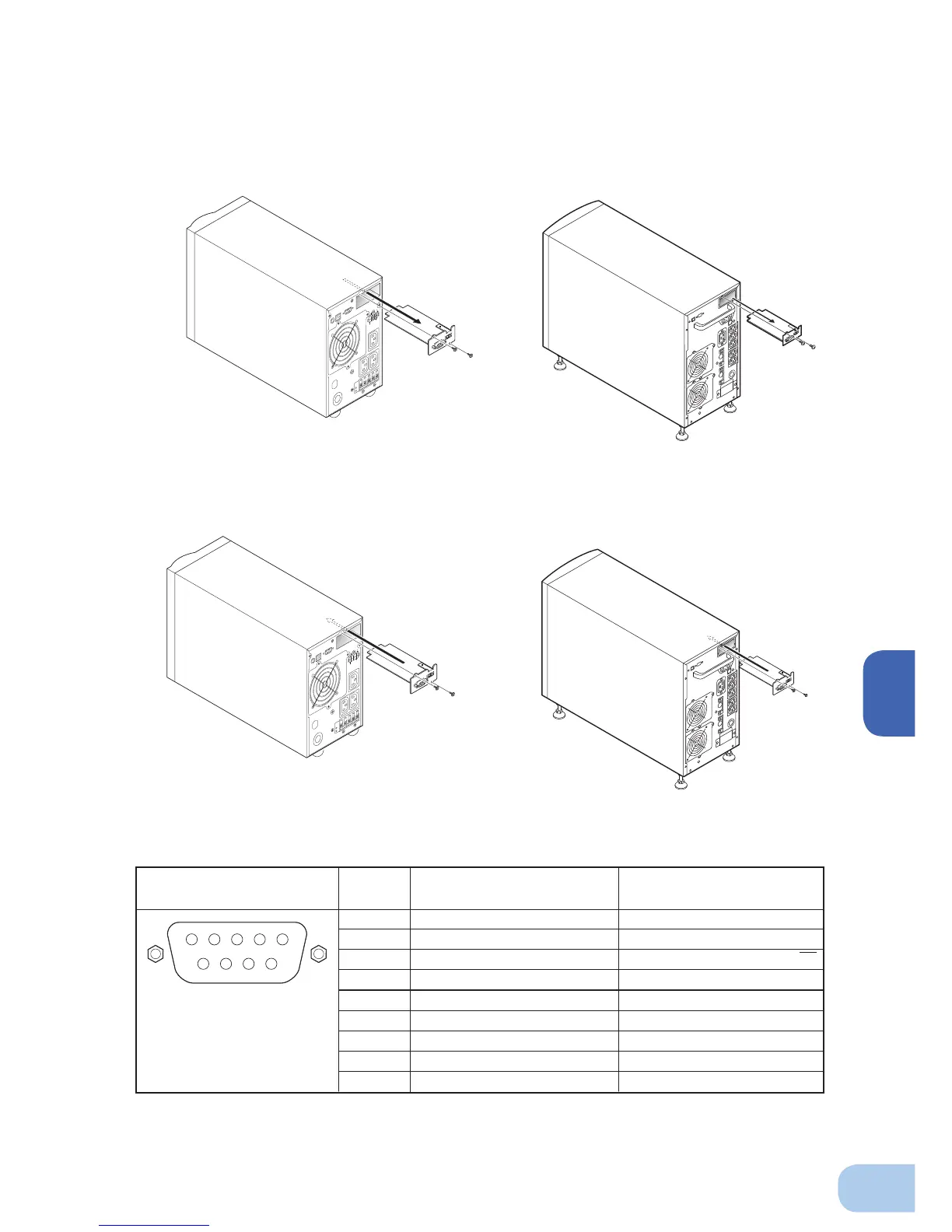
■
Insert/ removal method of contact signal card
(1) Turn OFF the power switch, remove the top and bottom screws (2 screws) of the contact signal connector
on the back of the unit, and carefully remove the contact signal card.
(2) After changing the settings, carefully reinsert the contact signal card and securely tighten the 2 screws.
5 4 3 2 1
9 8 7 6