129
Setting Tag Data Links Section 6-2
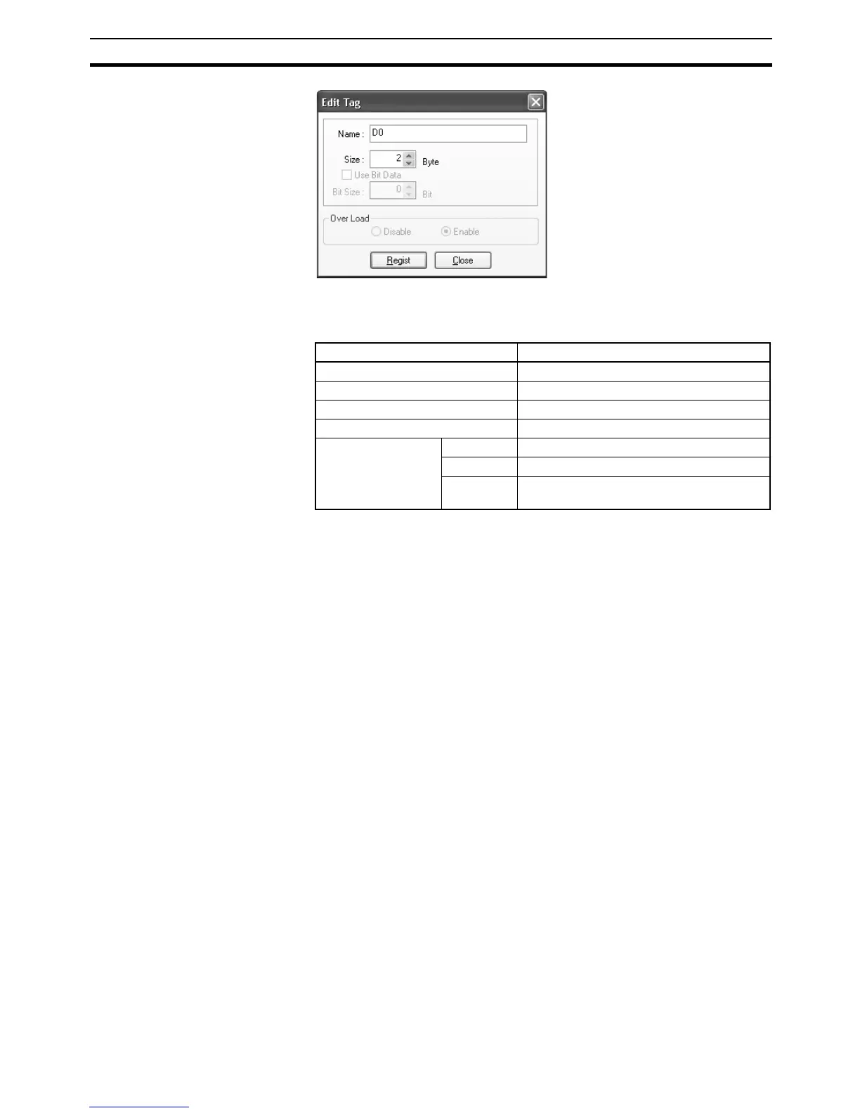
5. In the Name Field, enter the character string for the CPU Unit's I/O memory
address or a network symbol (e.g., 100, W100, D0, Input_signal).
Addresses in the following I/O memory areas can be set.
Note (a) The H, W, D, and E characters can also be input in lower case as
h, w, d, and e.
(b) Be sure to directly enter the CPU Unit's I/O memory address
(e.g., 100, W100, D0) or a network symbol as a character string.
6. Input the size of the tag in the Size Field, in bytes.
7. Click the Regist Button to register the tag.
If an I/O memory address is specified for a tag name, the Edit Tags Dialog
Box will be displayed with the next consecutive address as the tag name
for editing the next tag. Once you have registered the tags, click the Cancel
Button.
8. Click the Out - Produce Tab, and click the New Button. The Edit Tag Dialog
Box will be displayed, like the dialog box for input tags, except for the Over
Load setting. The Over Load setting determines whether outputs are
cleared or continue their previous status when outputs are turned OFF with
the PLC’s Output OFF function. Output inhibit settings are not required for
input (reception) tag sets.
• Follow the output inhibit function: Enabled (default)
Output data is cleared to 0 when a PLC output inhibit occurs.
• Do not follow the output inhibit function: Disabled
Output data maintains its previous status even after a PLC output in-
hibit occurs.
CPU Unit’s data area Address (Text to input in Name Field.)
CIO Area 0000 to 6143
Holding Area H000 to H511
Work Area W000 to W511
DM Area D00000 to D32767
EM Area Bank 0 hex E0_00000 to E0_32767
···
···
Bank 18
hex
E18_00000 to E18_32767

 Loading...


