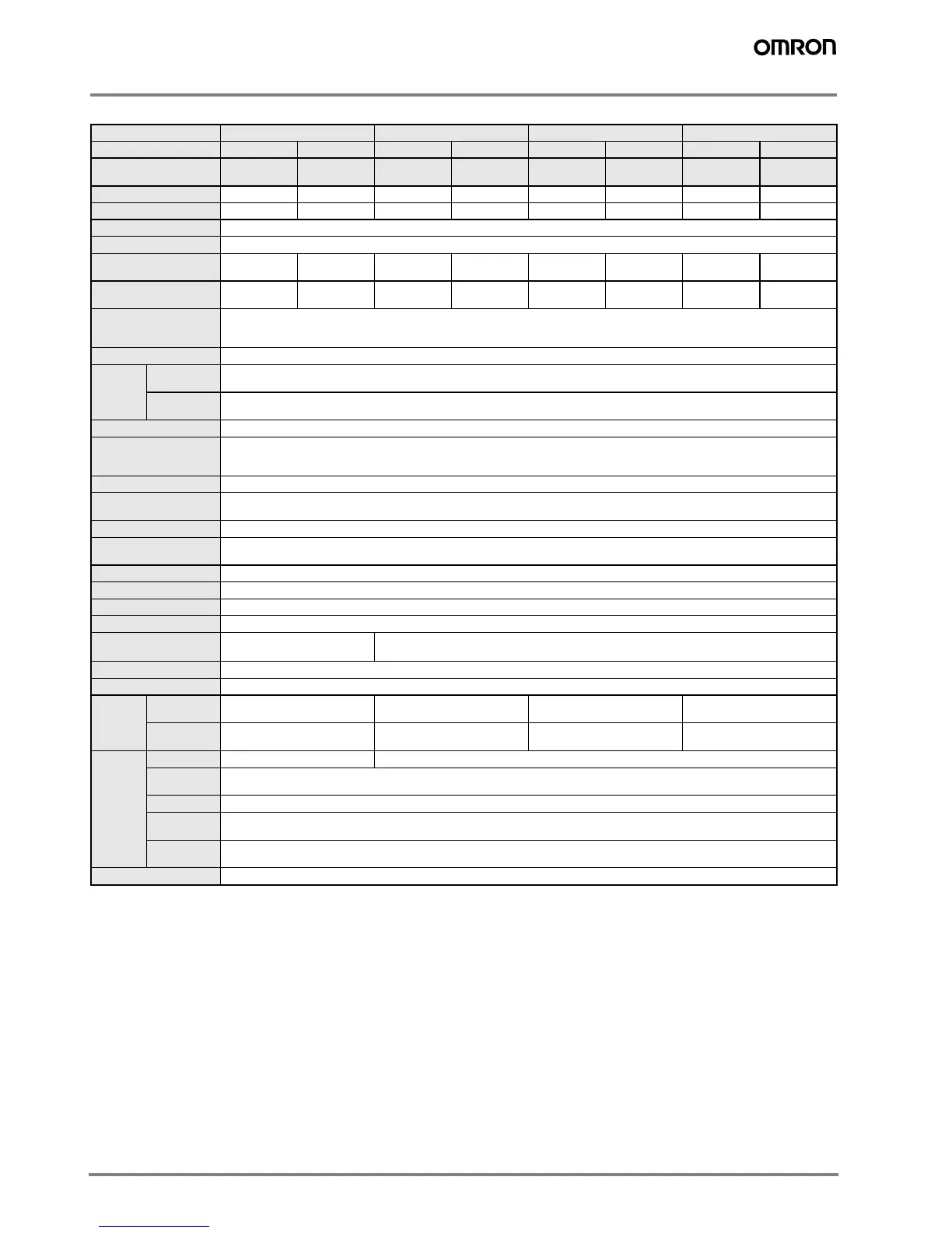
6 Inductive Sensors
E2E-X@E@/F@ DC 3-wire Models
Note: 1. The response speed is an average value. Measurement conditions are as follows: standard sensing object, a distance of twice the standard sensing object,
and a set distance of half the sensing distance.
2. When using an E2E with an M8 connector at an ambient temperature range between 70° C and 85° C, supply 10 to 30 VDC to the E2E and make sure that
the E2E has a control output of 100 mA maximum.
Size M8 M12 M18 M30
Type Shielded Unshielded Shielded Unshielded Shielded Unshielded Shielded Unshielded
Item E2E-X1R5E@/
F@
E2E-X2ME@/
F@
E2E-X2E@/
F@
E2E-X5ME@/
F@
E2E-X5E@/
F@
E2E-X10ME@/
F@
E2E-X10E@/
F@
E2E-X18ME@/
F@
Sensing distance 1.5 mm ±10% 2 mm ±10% 2 mm ±10% 5 mm ±10% 5 mm ±10% 10 mm ±10% 10 mm ±10% 18 mm ±10%
Set distance 0 to 1.2 mm 0 to 1.6 mm 0 to 1.6 mm 0 to 4.0 mm 0 to 4.0 mm 0 to 8.0 mm 0 to 8.0 mm 0 to 14.0 mm
Differential travel 10% max. of sensing distance
Sensing object Ferrous metal (The sensing distance decreases with non-ferrous metal, refer to Engineering Data.)
Standard sensing ob-
ject
Iron, 8 x 8 x
1mm
Iron, 12 x 12 x
1mm
Iron, 12 x 12 x
1mm
Iron, 15 x 15 x
1mm
Iron, 18 x 18 x
1mm
Iron, 30 x 30 x
1mm
Iron, 30 x 30 x
1mm
Iron, 54 x 54 x
1mm
Response speed (See
note 1.)
2.0 kHz 0.8 kHz 1.5 kHz 0.4 kHz 0.6 kHz 0.2 kHz 0.4 kHz 0.1 kHz
Power supply voltage
(operating voltage
range) (See note 2.)
12 to 24 VDC (10 to 40 VDC), ripple (p-p): 10% max.
Current consumption 13 mA max.
Control
output
Load current
(See note 2.)
200 mA max.
Residual
voltage
2 V max. (Load current : 200 mA, Cable length: 2 m)
Indicator Operation indicator (red LED)
Operation mode
(with sensing object ap-
proaching)
E1 F1 Models: NO
E2 F2 Models: NC
For details, refer to Timing Charts.
Protection circuits Power supply reverse polarity protection, surge suppressor, output load short-circuit protection
Ambient temperature
(See note 2)
Operating/Storage: –40° C to 85° C (with no icing or condensation)
Ambient humidity Operating/Storage: 35% to 95% (with no icing)
Temperature influence ±15% max. of sensing distance at 23° C in the temperature range of –40° C to 85° C
±10% max. of sensing distance at 23° C in the temperature range of –25° C to 70° C
Voltage influence ±1% max. of sensing distance in the rated voltage range ±15%
Insulation resistance 50 MΩ min. (at 500 VDC) between current-carrying parts and case
Dielectric strength 1,000 VAC at 50/60 Hz for 1 min between current-carrying parts and case
Vibration resistance 10 to 55 Hz, 1.5-mm double amplitude for 2 hours each in X, Y, and Z directions
Shock resistance
500 m/s
2
10 times each in X, Y,
and Z directions
1,000 m/s
2
10 times each in X, Y, and Z directions
Degree of protection IEC 60529 IP67 (Pre-wired models: JEM standard IP67g (waterproof and oil-proof))
Connection method Pre-wired models (standard length 2 m), connector models
Weight
(packed
state)
Pre-wired
models
Approx. 65 g Approx. 75 g Approx. 150 g Approx. 195 g
Connector
models
Approx. 15 g Approx. 25 g Approx. 40 g Approx. 90 g
Material Case Stainless steel (SUS303) Brass-nickel plated
Sensing sur-
face
PBT (
polybutylene terephthalate)
Cable PVC (polyvinyl chloride)
Clamping
nuts
Brass-nickel plated
Toothed
washer
Iron-zinc plated
Accessories Instruction manual
 Loading...