8 Standard Photoelectric Sensors
Operation
Output Circuits
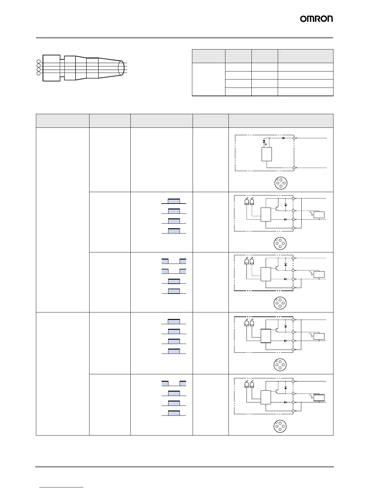
Structure of Sensor I/O Connector
PNP Output
Note: Terminal numbers for connector type.
1
2
3
4
Brown
White
Blue
Black
XS2F-D42#-D80-#
XS2F-G42#-G80-#
Classification Wire color Connector
pin No.
Use
DC Brown
➀
Power supply (+V)
White
➁
Mode selection Lon/Don
Blue
➂
Power supply (0 V)
Black
➃
Output
Model Output transistor
status
Timing chart Connection
method
Output circuit
E3F2-@B4-@
(except for
E3F2-LS10B4-@)
– – – Through-beam emitter
ON when light is
incident.
(Light-ON)
Connect the
pink (Pin
➁)
and brown
(Pin
➀) cords
or open the
pink cord
(Pin
➁).
ON when light is
interrupted.
(Dark-ON)
Connect the
pink (Pin
➁)
and blue
(Pin
➂) cords.
E3F2-LS10B4-@ ON when light is
incident.
(Light-ON)
Connect the
pink (Pin
➁)
and brown
(Pin
➀) cords
or open the
pink cord
(Pin
➁).
ON when light is
interrupted.
(Dark-ON)
Connect the
pink (Pin
➁)
and blue
(Pin
➂) cords.
Main
circuit
1
2
3
4
1
3
Connector Pin Arrangement
10 to 30 VDC
0 V
Brown
Blue
Power
indicator
(red)
Incident
Interrupted
ON
OFF
ON
OFF
Operate
Release
Output
indicator
(red)
Output
transistor
Load
(relay)
Light
indicator
Red
Main
circuit
1
2
3
4
1
2
3
4
Connector Pin Arrangement
10 to 30 VDC
100 mA
max.
Load
0 V
Mode selection
Brown
Black
Blue
Pink
Z
D
Z
D
: V
Z
= 36 V
Stability
indicator*
Green
* Only on models
E3F2-R4B4-@ and
E3F2-D1B4-@
Incident
Interrupted
ON
OFF
ON
OFF
Operate
Release
Output
indicator
(red)
Output
transistor
Load
(relay)
Light
indicator
Red
Main
circuit
1
2
3
4
1
2
3
4
Connector Pin Arrangement
10 to 30 VDC
100 mA
max.
Load
0 V
Mode selection
Brown
Black
Blue
Pink
Z
D
: V
Z
= 36 V
Stability
indicator*
Green
* Only on models
E3F2-R4B4-@ and
E3F2-D1B4-@
Incident
Interrupted
ON
OFF
ON
OFF
Operate
Release
Output
indicator
(orange)
Output
transistor
Load
(relay)
Output
indicator
Stability
indicator*
Orange
Main
circuit
1
2
3
4
1
2
3
4
Connector Pin Arrangement
10 to 30 VDC
100 mA
max.
Load
0 V
Mode selection
Brown
Black
Blue
Pink
Z
D
Z
D
: V
Z
= 36 V
Green
Incident
Interrupted
ON
OFF
ON
OFF
Operate
Release
Output
indicator
(orange)
Output
transistor
Load
(relay)
Output
indicator
Stability
indicator*
Orange
Main
circuit
1
2
3
4
1
2
3
4
Connector Pin Arrangement
10 to 30 VDC
100 mA
max.
Load
0 V
Mode selection
Brown
Black
Blue
Pink
Z
D
: V
Z
= 36 V
Green