E3M-V
E3M-V
5
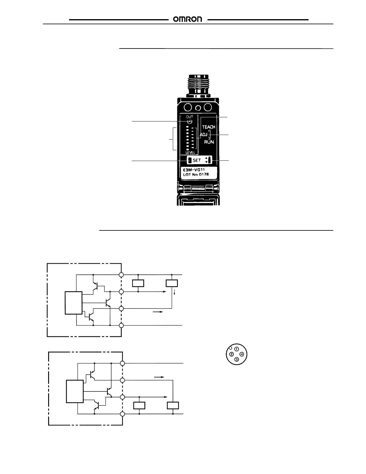
Nomenclature
E3M-V SENSOR
Operation Indicator (Orange)
Lit when the output is ON.
Detection Level Indicators (Green)
Displays the detection level.
SET Button
Used for teaching and threshold
adjustments.
Threshold Indicators (Red)
Displays the threshold level.
Mode Selector
Selects the mode.
UP/DOWN Selector
Increases the threshold value when
set to UP.
Decreases the threshold value when
set to DOWN.
Operation
OUTPUT CIRCUITS
Main
circuit
Remote control input
/Answer-back output
Load Load
Control
output
Brown
White
Black
Blue
Main
circuit
Load Load
10 to 30 VDC
Control
output
Brown
White
Black
Blue
(See note.)
(See note.)
Remote control input
/Answer-back output
NPN (E3M-VG11, E3M-VG21)
PNP (E3M-VG16, E3M-VG26)
10 to 30 VDC
Connector Pin Arrangement
1
2
4
3
1
4
2
3
100 mA max.
0 V
0 V
Note: Remote control input and answer-back output share the same line. Be sure to connect the load as shown above if the remote con-
trol function is used.