E3S
5
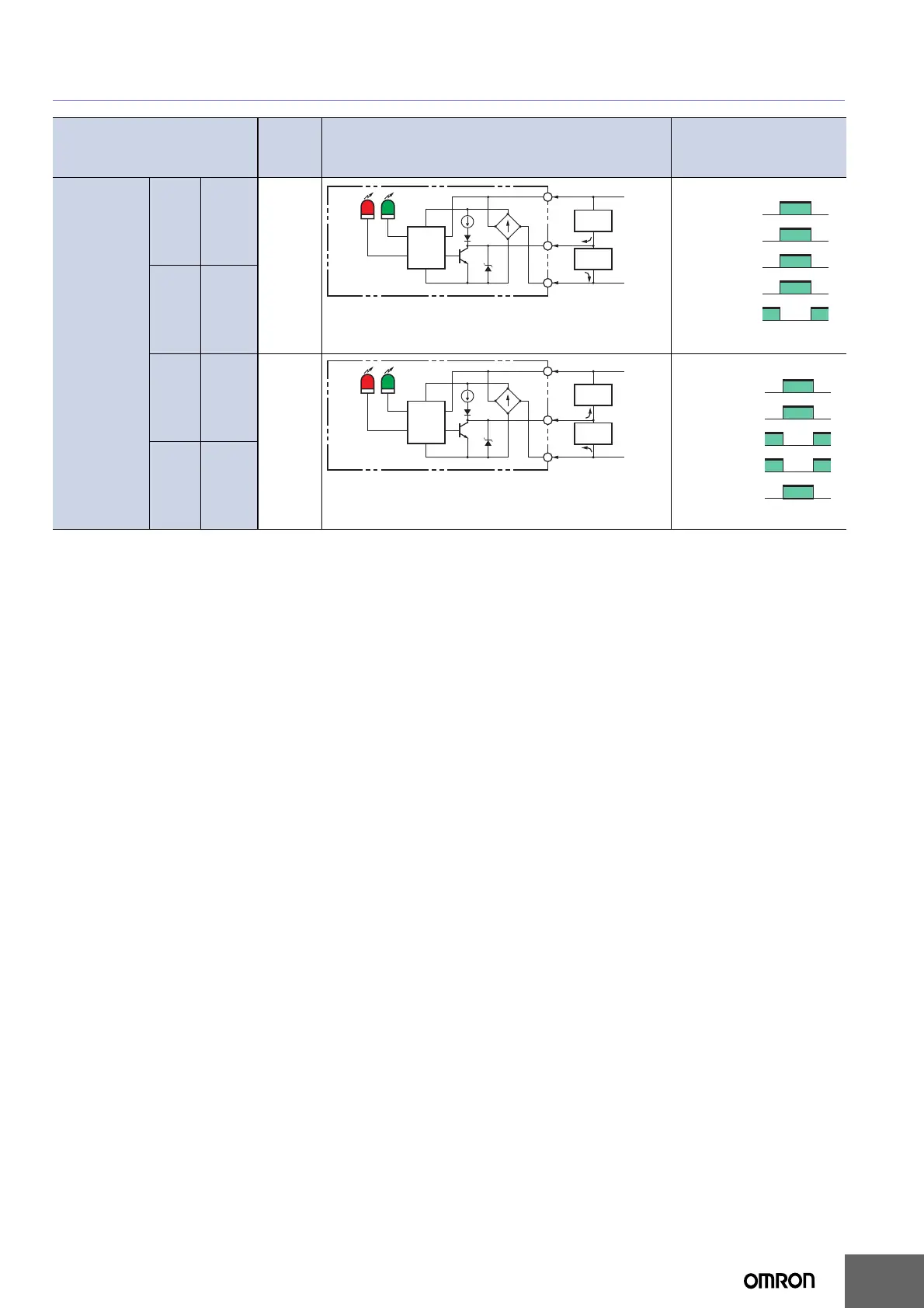
I/O Circuit Diagrams
Item
Opera-
tion
mode
Output circuit Timing charts
Model
Wire
color
Power
polarity
E3S
Brown +
Light-ON
Blue 0 V
Brown 0 V
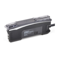
Dark-ON
Blue +
Brown *1
12 to 24 VDC
*2
0 V
Load 1
(relay)
Load 2
Black
Blue *1
1.5 to
4 mA
Z
Photo-
electric
Sensor
main
circuit
Stability
indicator
(green)
Light
indicator
(red)
Z: Zener diode (Vz = 30 V)
*1: Reverse the polarity of the power supply to switch the
operating mode.
*2: Voltage output (when connecting transistor circuit)
Incident light
No incident light
ON
OFF
ON
OFF
Operate
Reset
H
L
Light
indicator
(red)
Output
transistor
Load 1
(e.g., relay)
Load 2
(Between brown and black)
(Between blue and black)