4 Basic Operation
4 - 34
E5@C Digital Temperature Controllers User’s Manual (H174)
*1 With set values 1, 4, and 5, the upper- and lower-limit values can be set independently for each alarm
type, and are expressed as “L” and “H.”
*2 Set value: 1 (Upper- and lower-limit alarm)
*3 Set value: 4 (Upper- and lower-limit range)
*4 Set value: 5 (Upper- and lower-limit alarm with standby sequence)
• For the upper- and lower-limit alarms in cases 1 and 2 above, the alarm is always OFF if
upper- and lower-limit hysteresis overlaps.
• In case 3, the alarm is always OFF.
*5 Set value: 5 (Upper- and lower-limit alarm with standby sequence)
• The alarm is always OFF if upper- and lower-limit hysteresis overlaps.
*6 Refer to Standby Sequence Reset on page 6-64 for information on the operation of the standby
sequence.
*7 Refer to 5-11-1 Loop Burnout Alarm (LBA).
*8 Refer to PV Change Rate Alarm on page 4-36.
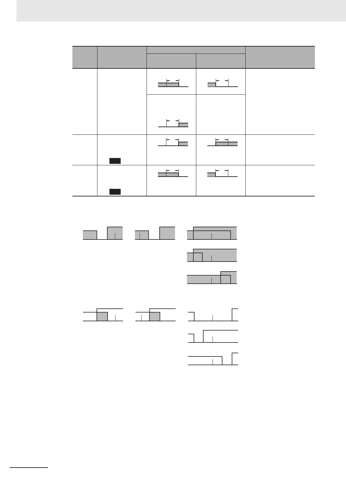
17 MV absolute-value
lower-limit alarm*9
Standard Control Standard Control This alarm type turns ON
the alarm when the
manipulated variable (MV)
is lower than the alarm
value (X).
Heating/Cooling
Control (Cooling
MV)
Heating/Cooling
Control (Cooling
MV)
Always ON
18 RSP
absolute-value
upper-limit alarm
*10
This alarm type turns ON
the alarm when the remote
SP (RSP) is higher than the
alarm value (X).
19 RSP
absolute-value
lower-limit alarm
*10
This alarm type turns ON
the alarm when the remote
SP (RSP) is lower than the
alarm value (X).
Set
value
Alarm type
Alarm output operation
Description of function
When alarm value
X is positive
When alarm value
X is negative
ON
OFF
0
X
MV
ON
OFF
0
X
MV
ON
OFF
RSP
0
X
ON
OFF
0
X
RSP
LHSP LHSP
H
LSP
H
LSP
H
LSP
H < 0, L > 0
|H| < |L|
H > 0, L < 0
|H| > |L|
H < 0, L < 0
H < 0, L > 0
|H| ≥ |L|
H > 0, L < 0
|H| ≤ |L|
Case 1
Case 2 Case 3 (Always ON)
LHSP
H
LSP
H
LSP
H
LSP
LHSP
H < 0, L > 0
|H| < |L|
H > 0, L < 0
|H| > |L|
H < 0, L < 0
H < 0, L > 0
|H| ≥ |L|
H > 0, L < 0
|H| ≤ |L|
Case 1
Case 2
Case 3 (Always OFF)
 Loading...


