A Appendices
A - 22
E5@C Digital Temperature Controllers User’s Manual (H174)
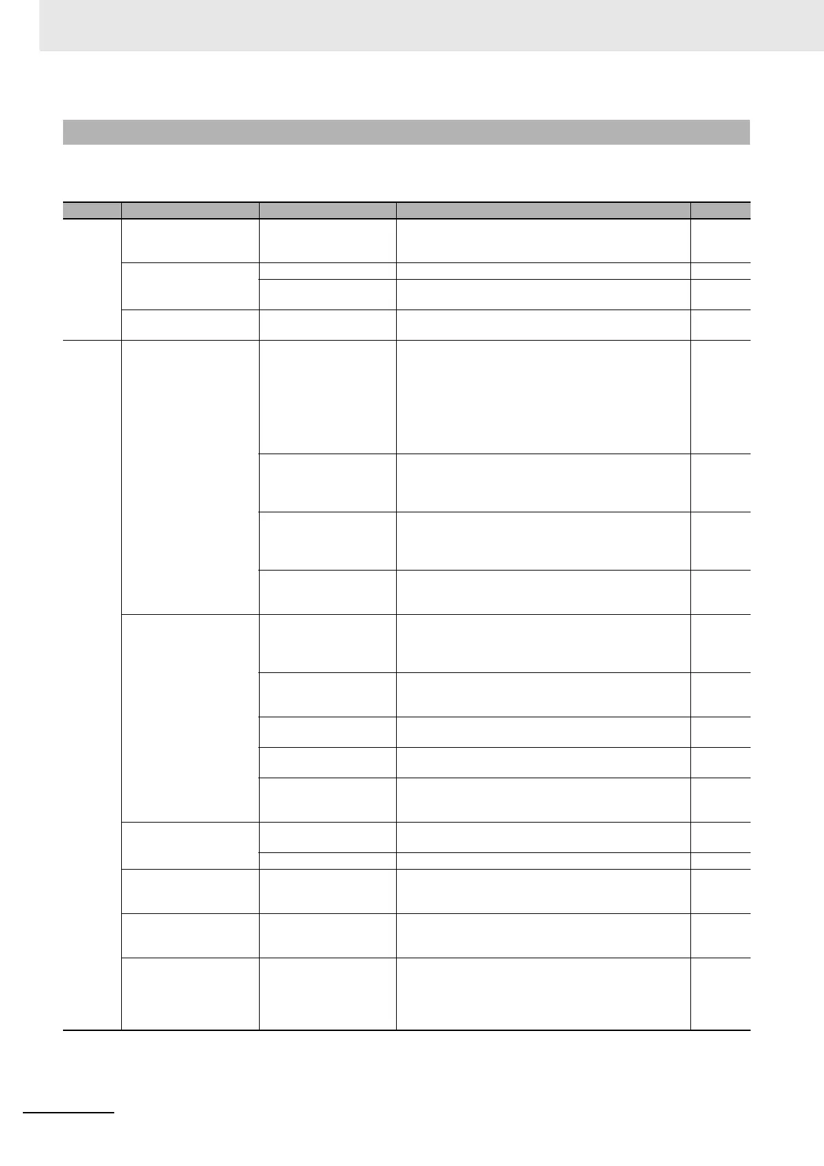
If the Digital Controller is not operating normally, check the following points before requesting repairs. If
the problem persists, contact your OMRON representative for details on returning the product.
*1 Also refer to the E5
@
C Digital Controllers Communications Manual (Cat. No. H175) for details.
A-5-2 Checking Problems
Timing Status Meaning Countermeasures Page
Turning
ON the
power for
the first
time
The TUNE indicator will
flash.
ST (self-tuning) is in
progress (default setting:
ON).
This is not a product fault.
The TUNE indicator flashes during self-tuning.
4-27
Temperature error is
large.
Input error (S.Err display)
Input type mismatch Check the sensor type and reset the input type correctly. 4-12
Thermometer is not
installed properly.
Check the thermometer installation location and polarity
and install correctly.
2-25,
2-41
Communications are not
possible.
Non-recommended
adapter is being used.
Make sure that the connected device is not faulty.
*
1
During
operation
Overshooting
Undershooting
Hunting
ON/OFF control is
enabled (default: ON/OFF
control selected).
Select PID control and execute either ST (self-tuning) or
AT (auto-tuning).
When using self-tuning, turn ON the power supply to the
Digital Controller and load (heater, etc.) at the same time,
or turn ON the load power supply first. Accurate
self-tuning and optimum control will not be possible if the
power supply to the load is turned ON after turning ON the
power supply to the Digital Controller.
4-24
Control period is longer
compared with the speed
of rise and fall in
temperature.
Shorten the control period. A shorter control period
improves control performance, but a cycle of 20 ms
minimum is recommended in consideration of the service
life of the relays.
4-15
Unsuitable PID constant Set appropriate PID constants using either of the following
methods.
• Execute AT (autotuning).
• Set PID constants individually using manual settings.
4-24
HS alarm operation fault Use breeder resistance if the problem is due to leakage
current. Also investigate the errors detected by the HS
alarm function.
4-42
Temperature is not rising Specified operation is
unsuitable for required
control (default: Reverse
operation).
Select either forward or reverse operation depending on
the required control. Reverse operation is used for heating
operations.
4-15
Heater is burnt out or
deteriorated.
Check whether heater burnout or deterioration have
occurred. Also investigate the errors detected by the
heater burnout alarm.
4-40
Insufficient heater
capacity
Check whether the heater's heating capacity is sufficient. ---
Cooling system in
operation.
Check whether a cooling system is operating. ---
Peripheral devices have
heat prevention device
operating.
Set the heating prevention temperature setting to a value
higher than the set temperature of the Digital Controller.
---
The AT Execute/Cancel
parameter (at) is not
displayed.
ON/OFF control is
enabled.
Set the PID ON/OFF parameter to PID. 6-45
The Controller is stopped. Set the RUN/STOP parameter to RUN. 6-13
The SP Ramp Set Value
parameter (sprt) is not
displayed.
ST is enabled Set the ST parameter to OFF. 6-33
The Remote SP Enable
parameter (rspu) is not
displayed.
ST is enabled Set the ST parameter to OFF. 6-85
The Alarm 1 Type
parameter (alt1) is not
displayed.
The Auxiliary Output 1
Assignment parameter is
set to a heater alarm for a
Controller with heater
burnout detection.
Set the Auxiliary Output 1 Assignment parameter to Alarm
1. The default setting is for a heater alarm (HA).
6-83
 Loading...


