5 Advanced Operations
5 - 74
E5@C Digital Temperature Controllers User’s Manual (H174)
Example: When Work Bit 1 (WR1) Is ON for the PV Status Display Function (Registered Message:
WR1)
Status Display Message Specifications
• You can use up to four of the following characters: A to Z, 0 to 9, spaces, and hyphens.
• If nothing is entered in the message field or if all spaces are set, the message is disabled and
nothing is displayed.
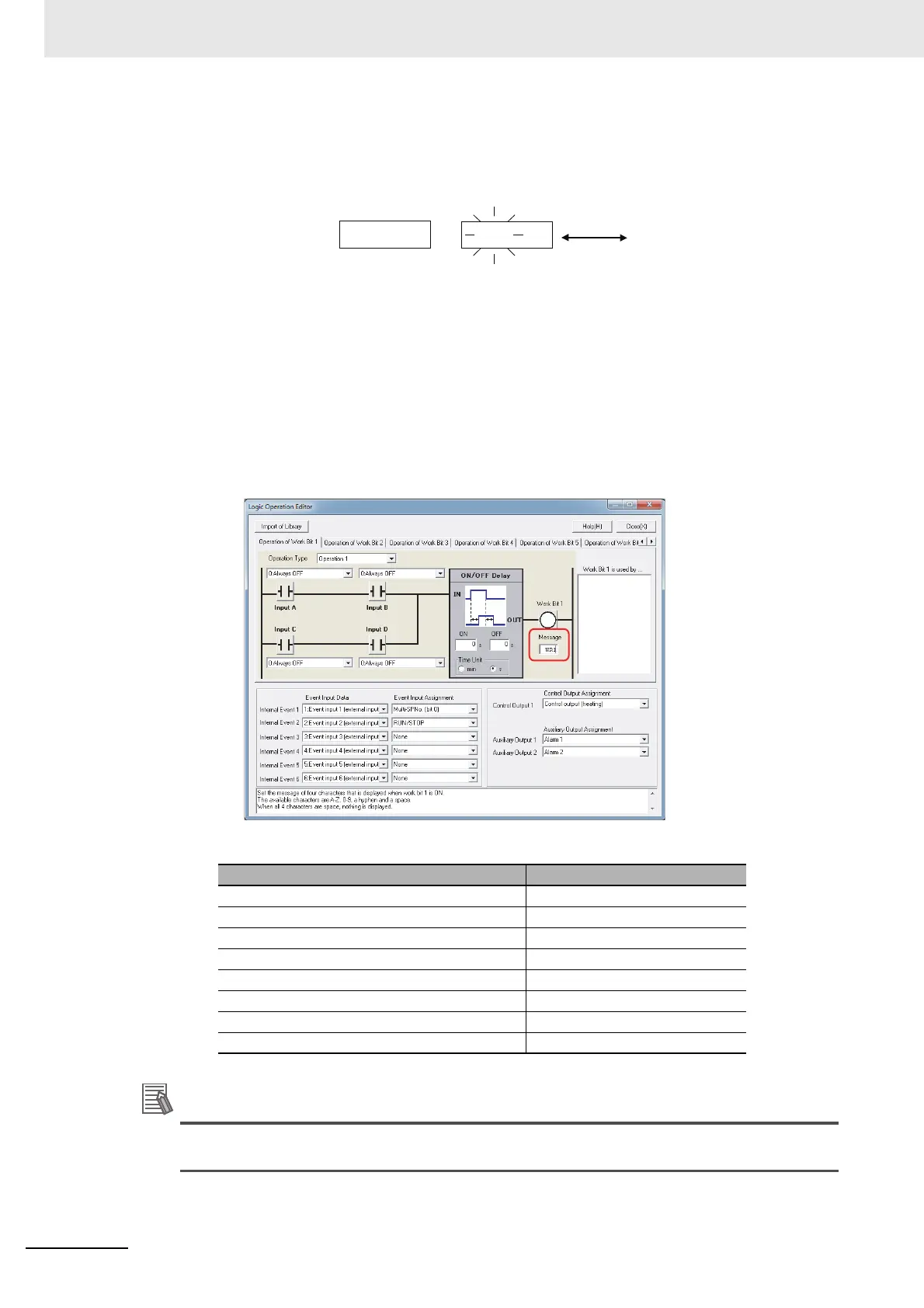
Operating Procedure
1
On the Logic Operator Editor, enter the message in the input field for the work bit as
shown in the following figure.
The default message settings for the work bits are given in the following table.
* Underbars in the default messages indicate spaces.
Status Display Message Priority
The status display message for the highest bit number that is ON is given priority.
Name Default*
Work Bit 1 Status Display Message _WR1
Work Bit 2 Status Display Message _WR2
Work Bit 3 Status Display Message _WR3
Work Bit 4 Status Display Message _WR4
Work Bit 5 Status Display Message _WR5
Work Bit 6 Status Display Message _WR6
Work Bit 7 Status Display Message _WR7
Work Bit 8 Status Display Message _WR8
25
25
100
PV/SP
Alternating
display
Normal operation
wr1
100
Work bit 1 (WR1)
is ON
 Loading...


