A - 35
A Appendices
E5@C Digital Temperature Controllers User’s Manual (H174)
A-6 Parameter Operation Lists
A
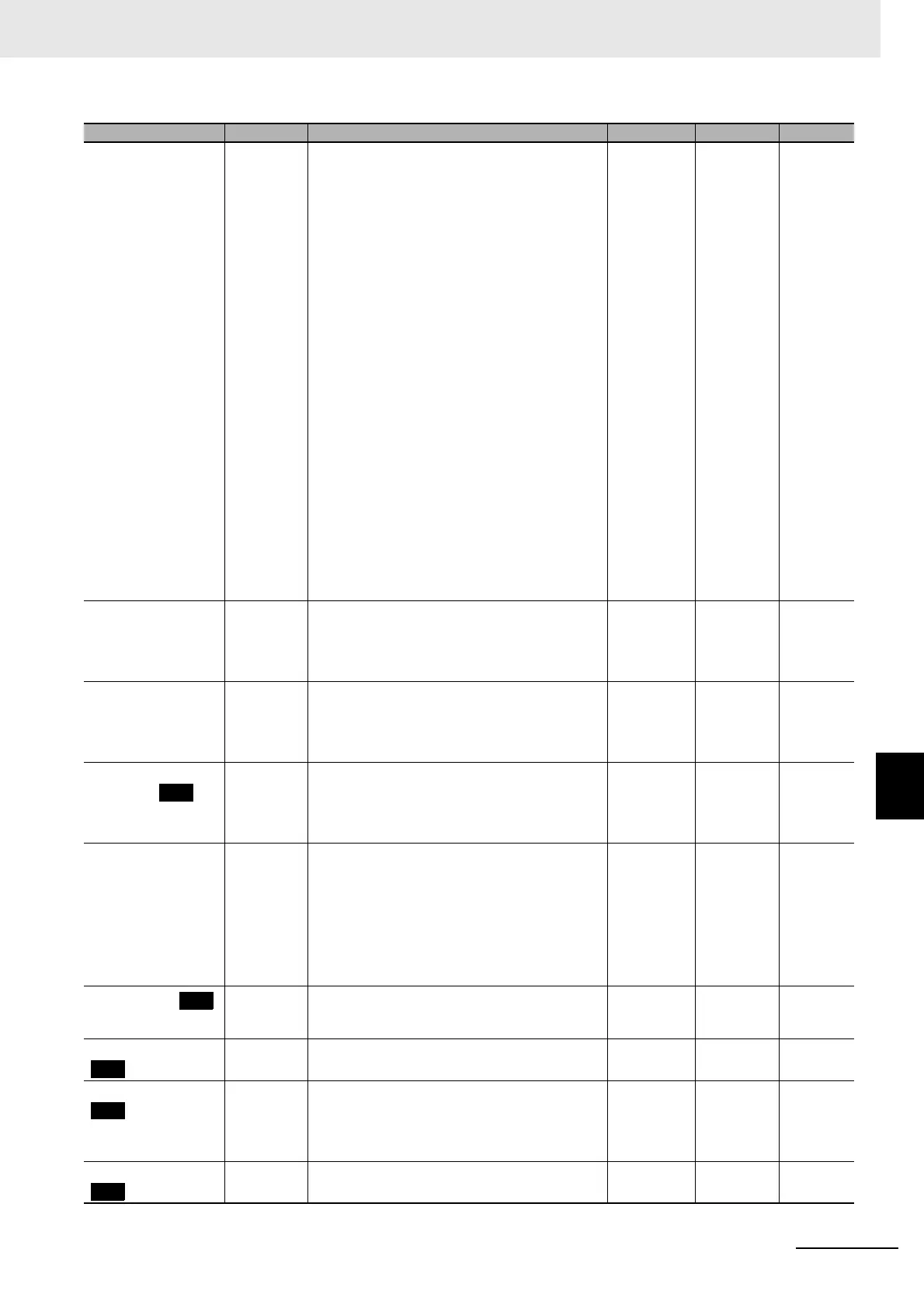
A-6-6 Advanced Function Setting Level
Auxiliary Output 1
Assignment
sub1 NONE: No assignment none ALM1
*Digital
Controllers
without HB
and HS
alarm
detection:
HA
None
O: Control output (heating) o
C-O: Control output (cooling) c-o
ALM1: Alarm 1 alm1
ALM2: Alarm 2 alm2
ALM3: Alarm 3 alm3
ALM4: Alarm 4 alm4
HA: Heater alarm (HB + HS) ha
HB: Heater burnout alarm (HB) hb
HS: Heater short alarm (HS) hs
S.ERR: Input error s.err
RS.ER: RSP input error rs.er
P.END: Program end output
*3
p.end
RUN: RUN output run
ALM: Integrated alarm alm
WR1: Work bit 1
*4
wr1
WR2: Work bit 2
*4
wr2
WR3: Work bit 3
*4
wr3
WR4: Work bit 4
*4
wr4
WR5: Work bit 5
*4
wr5
WR6: Work bit 6
*4
wr6
WR7: Work bit 7
*4
wr7
WR8: Work bit 8
*4
wr8
Auxiliary Output 2
Assignment
sub2 Same as the Auxiliary Output 1 Assignment
parameter.
Same as the
Auxiliary
Output 1
Assignment
parameter.
ALM2 None
Auxiliary Output 3
Assignment
sub3 Same as the Auxiliary Output 1 Assignment
parameter.
Same as the
Auxiliary
Output 1
Assignment
parameter.
ALM3 None
Auxiliary Output 4
Assignment
sub4 Same as the Auxiliary Output 1 Assignment
parameter.
Same as the
Auxiliary
Output 1
Assignment
parameter.
ALM4 None
Integrated Alarm
Assignment
alma 0 to 255
Alarm 1: +1
Alarm 2: +2
Alarm 3: +4
Alarm 4: +8
HB alarm: +16
HS alarm: +32
Input error: +64
RSP input error: +128
49 None
Soak Time Unit
t-u M: Minutes
H: Hours
S: Seconds
*6
m, h M None
Alarm SP Selection alsp SP-M: Ramp set point
SP: Set point
sp-m, sp SP-M None
Remote SP Input rs-t 4-20: 4-20 mA
0-20: 0-20 mA
1-5V: 1-5 V
0-5V: 0-5 V
0-10: 0-10 V
4-20, 0-20,
1-5V, 0-5V,
0-10
4-20 None
Remote SP Enable rspu OFF, ON off, on OFF None
Parameters Characters Setting (monitor) value Display Default Unit
 Loading...


